I was actually considering tucking a tiny relay into the car for just that reason, nothing connected, just a clicker, but I dismissed the idea and settled on a progressive turn signal style.

I make it to him and got $30. ![]()
It's a very cool turn signal, but you have chance to make a click sound even if you adopted it!
Have you ever heard thousands of relays clicking together? It's quite spectacular.

Maybe I can get Fujitsu to sponsor my much smaller relay computer some day.
I added a 2nd capacitor to pull down the N-MOS faster as well.
I updated the references from left to right, then top to bottom.
Landed on the IRF4095 for the P-MOS. It's about $0.65, readily available, and I think it will serve the purpose for the 2S and 4S models.

Okay, I’m not going back to find out why C1 and C2 are in the circuit.
But why are C1 and C2 in the circuit.
Because the power supply works perfectly powered up or powered down, but when it's been allowed to settle while disconnected from power and is reconnected the P-MOS doesn't clamp down fast enough given its isolator caps. I figured this morning that the N-MOS being pulled down faster will also help, I think anyway.

C1 slows down switching speed.
It's the same as MOSFET's Ciss.
1 Like
So C2 is good and C1 is bad?
Does it function differently than opposite with an N-MOS?
C1 will slow the switching of Q1.
C2 is a short circuit when Q1 first turns on or when SW1 is pressed ouch.
Where is your fuse ?
If you need to N-MOS has the same function, the circuit will be different.
Must be installed in parallel with R2.
However, the gate damping resistance value is low and the parasitic capacitance of BS170 is small, so it may have little effect.
I'm still spit-balling.
C1 is clearly a bad idea.
I see then. Between the pin and the gate.
Now that you mention the size I do remember you saying yesterday that this effect increases with size. I should have applied the same fact backwards.
Why D1 ?

So the square wave is preferable and my cap messes that up.
Yes
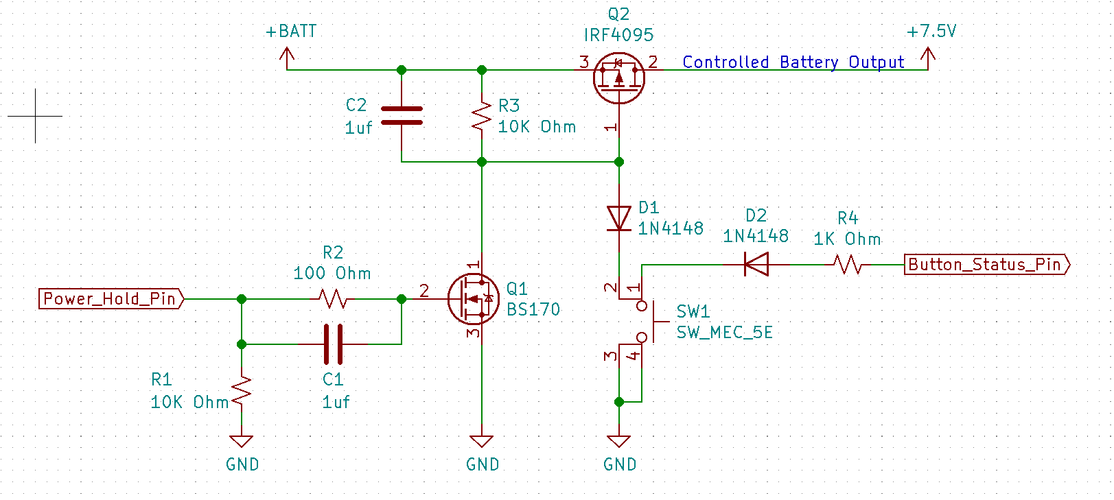
I suggest you get rid of C1, C2 and D1.
D1 and D2 together allow the pin to read the button state without reading if the N-MOS is grounded as well. At least that's how I see it.
D2 yes but D1 serves no purpose.