I've got a project planned for building a small scale steam powered electrical generator.
What I've got in mind is having the arduino controlling the water/steam flows through multiple stop taps as well as the air flow from the heat source to the tanks and these objects are triggered based on temperature and pressure readings that the arduino is monitoring either in real-time or at set intervals depending on its run cycle phase.
What I'm not sure of is which arduino and shields to use to do this for 13 pressure meter inputs, 2 temperature sensor inputs and 15 servo outputs. Although if anyone knows if there's an arduino compatible stoptap/psi meter combined that will reduce the inputs/outputs needed it would combine the pressure sensor inputs and 13 of the servo outputs.
You have not told us what Arduino experience you have so I may be teaching granny to such eggs.
You need to deal with this in much smaller chunks.
Figure out how to read the pressure sensor and the temperature sensor with very small programs.
Without seeing the datasheets for the sensor it is impossible to know how many Arduino I/O connections would be needed or whether analog or digital pins are needed.
You will be extremely luck to find another Forum member who is familiar with the hardware for a project like this. I reckon you need to do your own research. Maybe there are other steam engine forums that could help. For example, radio control is common for steam powered garden railways.
...R
Planning and Implementing a Program
Robin2:
You have not told us what Arduino experience you have so I may be teaching granny to such eggs.
You need to deal with this in much smaller chunks.
Figure out how to read the pressure sensor and the temperature sensor with very small programs.
Without seeing the datasheets for the sensor it is impossible to know how many Arduino I/O connections would be needed or whether analog or digital pins are needed.
You will be extremely luck to find another Forum member who is familiar with the hardware for a project like this. I reckon you need to do your own research. Maybe there are other steam engine forums that could help. For example, radio control is common for steam powered garden railways.
...R
Planning and Implementing a Program
I've never owned an Arduino before but I've been researching them quite a bit over the last few months and it should be more than capable of handling what I want it to do with the correct coding I'm just unsure of which Arduino to use because I'm not familiar enough with the different types. The requirements are:
- 13 Analog inputs connected to PSI sensors
- 2 Analog inputs connected to temperature sensors
- 15 Digital outputs connected to servo motors
I understand that it's a complex project I'm doing but the part that involves the Arduino actually seems to be the simplest part out of everything, all I'm really looking to make it do is monitor 13 inputs and whenever one reaches a defined point output a signal on the appropriate connection. The same thing could be desired from automated lights being run on photocells. I've already started working on the furnace section that's going to be providing the heat but I was originally going to be running it on manual taps and traditional analog PSI gauges but it seems rather inefficient and there's always the risk of the pipework or tanks rupturing if it's left running unattended for too long and I've been thinking of something I could apply Arduino to for a while now because I'd love to get into them so this just seems to fit.
I just want to make sure I understand the point of this project. What you're proposing is not replacing the mechanical gearbox and controls with a digital version, but replacing the engineer/driver/operator who is monitoring the engine, pressures and speeds with an Arduino that can shut off valves to prevent over-pressures and explosions. Do I have that correct?
Can you provide a simple drawing showing why you need so many sensors and what the servos will be doing?
Paul
blackblt1:
I just want to make sure I understand the point of this project. What you're proposing is not replacing the mechanical gearbox and controls with a digital version, but replacing the engineer/driver/operator who is monitoring the engine, pressures and speeds with an Arduino that can shut off valves to prevent over-pressures and explosions. Do I have that correct?
Kinda the generator itself isn't going to have a gearbox because it's just steam turbines that will have magnets as a part of the rotating segment so there's no need for a gearbox, it's to test out the tesla turbine design.
The only "moving" parts are:
-
Heated air being provided by a large rocket stove, a water inlet which will is going to be controlled by a float valve similar to the one's you find in toilets but this one is suitable for heated tanks.
-
The shutters on the two air pipes from the rocket stove.
-
The Turbine Disks
-
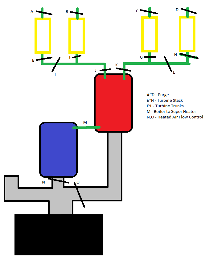
The stop taps which are:
-
Boiler -> Steam Super Heater
-
Steam Super Heater -> Turbine Trunk A
-
Steam Super Heater -> Turbine Trunk B
-
Steam Super Heater -> Turbine Trunk C
-
Steam Super Heater -> Turbine Trunk D
-
Turbine Trunk A -> Turbine Stack A
-
Turbine Trunk B -> Turbine Stack B
-
Turbine Trunk C -> Turbine Stack C
-
Turbine Trunk D -> Turbine Stack D
-
Turbine Stack A -> Purge A
-
Turbine Stack B -> Purge B
-
Turbine Stack C -> Purge C
-
Turbine Stack D -> Purge D
Paul_KD7HB:
Can you provide a simple drawing showing why you need so many sensors and what the servos will be doing?
Paul
It's a very quick and dirty diagram I've just thrown together in mspaint because it's past 2am for me so no energy to do anything fancier but that's the basics of what I'm doing if I have to draw it 2D showing all the working parts, everywhere a black line crosses something else on a slant is where there's a servo motor and I've labelled what they are in relation to the list above. The air flow control ones are basically just metal disks inside the duct that rotate on a rod that I could put a manual lever on or stick a gear on it that pairs to a servo with a gear or maybe just weld the servo rod onto it I don't know how well that'll work though with something like a cheap servo motor with plastic housing etc., then the stop taps would be paired up with the pressure meters sitting on the inlet side and the servo controlling the stop tap while the meter sends the signal to the Arduino.
I guess it must be late at night, but good drawing. You are confusing me by using steam sometimes and air at others.
I recall a Tesla turbine construction article years ago in a Home Shop Machinist magazine. I will have to look in the shop tomorrow to see if I can find it.
Have you determined how fast you need to make each valve/control operate?
Paul
I see now. I was thinking steam piston and not turbine. That would be a perfect application for Arduino. You plan on regulating the speed based on how open or closed the valves are. BTW, we call those butterfly valves here in the states. Anyways, you really don't want to use butterfly valves for your project. At those pressures, they're pretty much binary, or either fully on or fully off. You'll need either a ball, gate or piston valve. Probably the piston valve is your best bet for regulating the pressures and speed. Normally, a spring loaded piston valve is called a "regulator" since the compression on the spring can be increased or decreased by a screw with a knob.
Anyways, you'll want to scrap the butterfly valve plan. Use the piston valve for pressure regulation, but use a ball valve for pressure relief. A ball valve works similar to a butterfly valve but instead of a flat plate, it uses a steel ball with a hole drilled through it. The ball is rotated in the valve so that in the open position, the air/steam moves through the hole and in the closed position, the hole is 90 degrees to the flow.
As far as inputs are concerned, I see you'll need a temperature, pressure, volume, and electrical output readings. Temperature and pressure should be easy to work out. Stick a probe in the bottom of your boiler plumbed through a plug of some kind. Same with the pressure. Volume could get tricky, since most float based systems I know of use a pot to change resistivity and that is how volume is read, by measuring resistivity. Last I checked, those things are heat sensitive. You may want to rig up some kind of separate tank to hold the float that is plumbed to the boiler to measure the height of the water, but away from the heat to protect the pot. As for electrical output, I'd say that would take more experience than I have. But I'm sure you'll figure it out.
To help make things easier, I'd lay out a logic diagram of how you want each action to work, showing all your constraints and the subsequent actions. That should help you break things down and just right each action as a separate set of instructions. For instance, speed control could have an input from the electrical output, to increase or decrease the pressure to the generator. That should help simplify things for you.
Good luck. Looking forward to seeing how this works out.
CrafDee1:
I'm not familiar enough with the different types. The requirements are:
- 13 Analog inputs connected to PSI sensors
- 2 Analog inputs connected to temperature sensors
- 15 Digital outputs connected to servo motors
If you look at the specs for the Mega you will see that it has a max of 16 analog inputs. I don't think any other Arduino has more.
Are you sure that the sensors you want to use produce an analog rather than a digital output?
As I mentioned earlier you need to post links to the datasheets for the sensors so we can see what you are talking about.
...R