Hi! Let me know if this has already been answered, but I'm having a hard time finding the kind of MOSFET I'd need to drive 30 solenoids from an Arduino. The solenoids are 20 VDC, 2 amp. At least I think they're that, I couldn't find a datasheet for them. When I use a multimeter it read 18 VAC, ~2 amps.
The few MOSFETs I've looked at look like they'll overheat with anything that high. I am trying to avoid spending too much (to get enough SSRs it was looking like $150) but if just is expensive, I can make do
It'll also be my first time wiring them up, would anyone know of a good wiring tutorial?
The solenoids say 20V DC and you measured 18V AC ?
If you did not find a datasheet for the solenoids it still would be helpful to post a picture of them.
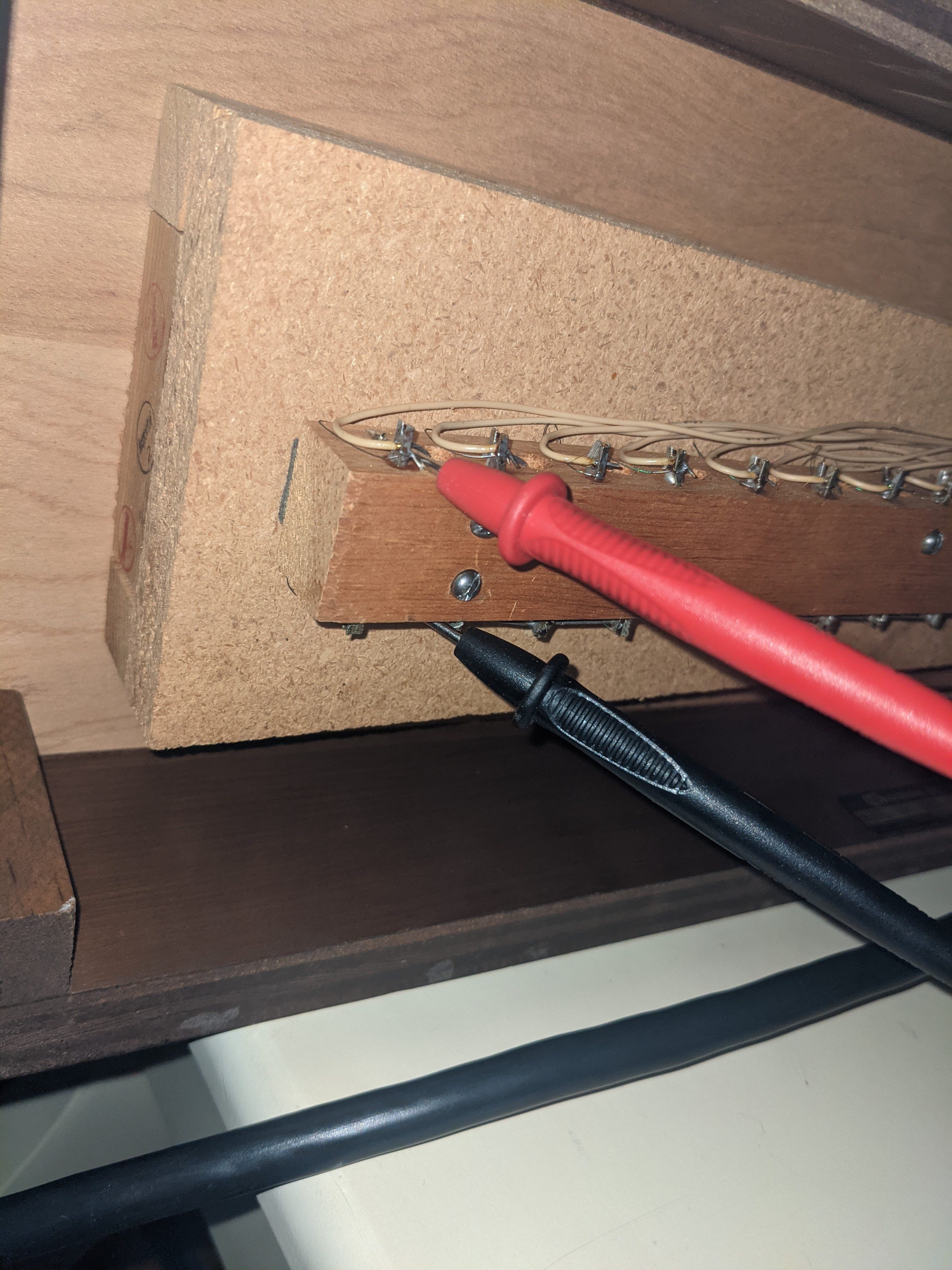
additional post a picture of the powered solenoid with your multimeter. This picture should show:
the complete wiring: both wires from power-supply to your multimeter to the solenoid in a way that it is easy to see what is connected to what.
this picture should show the switch on your multimeter that it can be easily seen what measure-option you have on the multimeter and the measured value of course.
It is very unlikely that a MOS-FET will overheat at a current of 2A.
There are a lot of MOS-FETs that can easily deal with 20A or 60A or 100A
First thing to do is to clear if you are using an AC-powersupply or a DC-powersupply
Unless you need very fast switching or any kind of PWM, I always wonder why people wish to switch big (mechanical) loads with MOSFETs. In this case you are powering solenoids.
Yes, in some ways MOSFETs are more elegant design, but as you have seen it can be a tricky problem.
For these sort of projects, I would tend to use a relay. And then switch that relay with a very small MOSFET. This is the very application for which relays are intended.
The reality is that a relay solution won't generate the heat and won't need heatsinks. In many cases the relay solution can be more compact (especially no heatsinks) - and it will likely be cheaper.
Sorry to put a damper on the MOSFET idea, but why not use a relay?
If you do, don't forget to add a flyback diode in reverse polarity across the relay coil (which I would assume you have across the solenoids anyway).
I hope this helps.
How many do you need turned on at one time?
I offer a board with 32 logic level MOSFETs with low Rds and high current ratings,
such as AOD514. The outputs have a 2A rated diode from output to supply, so diodes across your relays coils may not be needed, but would be a good idea.
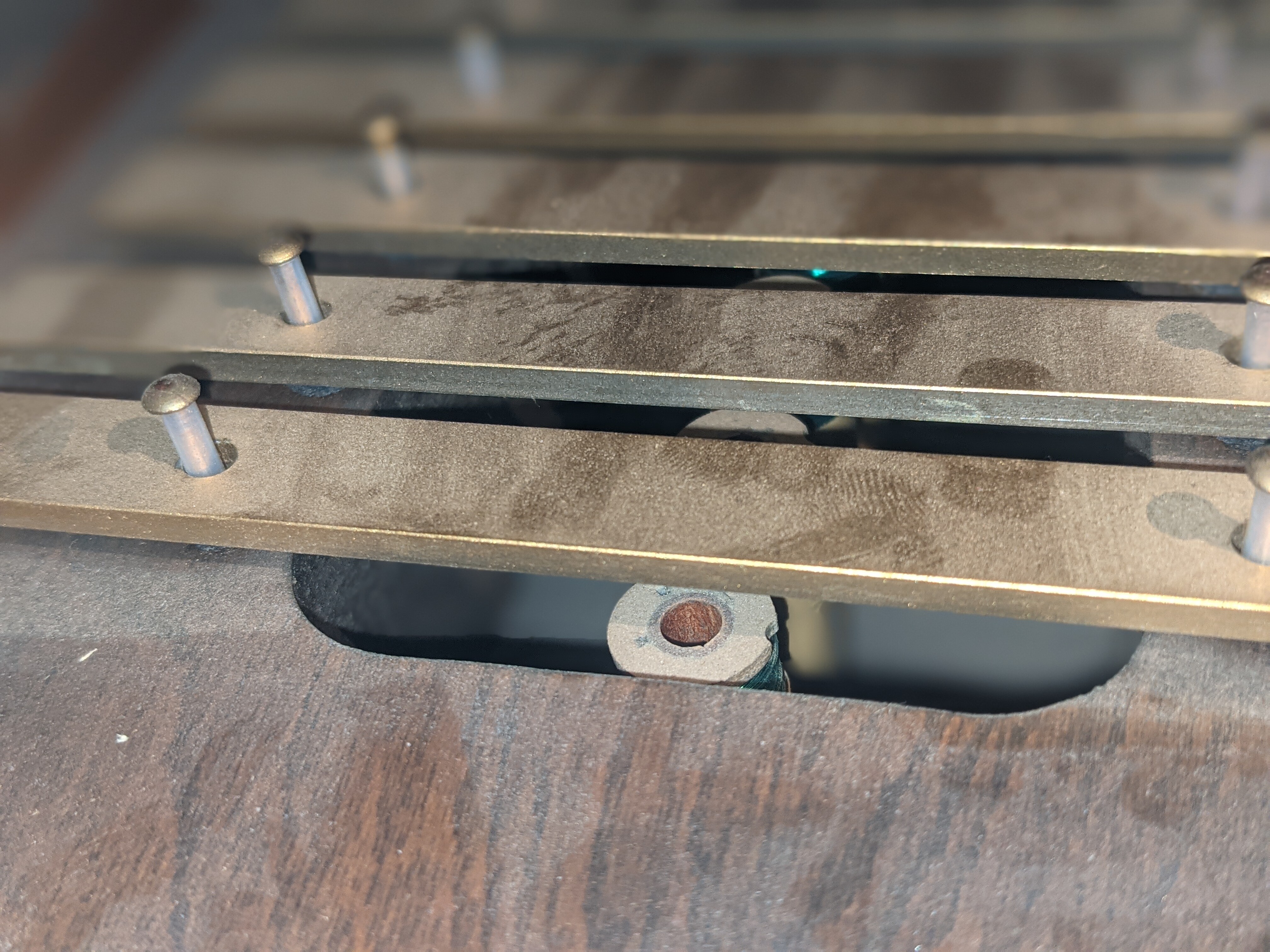
For the most part, reading the keys is easy, but not so for driving the solenoids, due to their high energy demand. I don't know if they're true solenoids. From what I can tell the coil is partially suspended and has a rod resting at the bottom. When it gets energized the rod shoots up and strikes the chime. These were the best pictures I could get of it:
I managed to misplace my voltmeter, but it said 18 VAC . I didn't have the equipment to measure amperage, but I used measurements that someone else took on a similar setup.
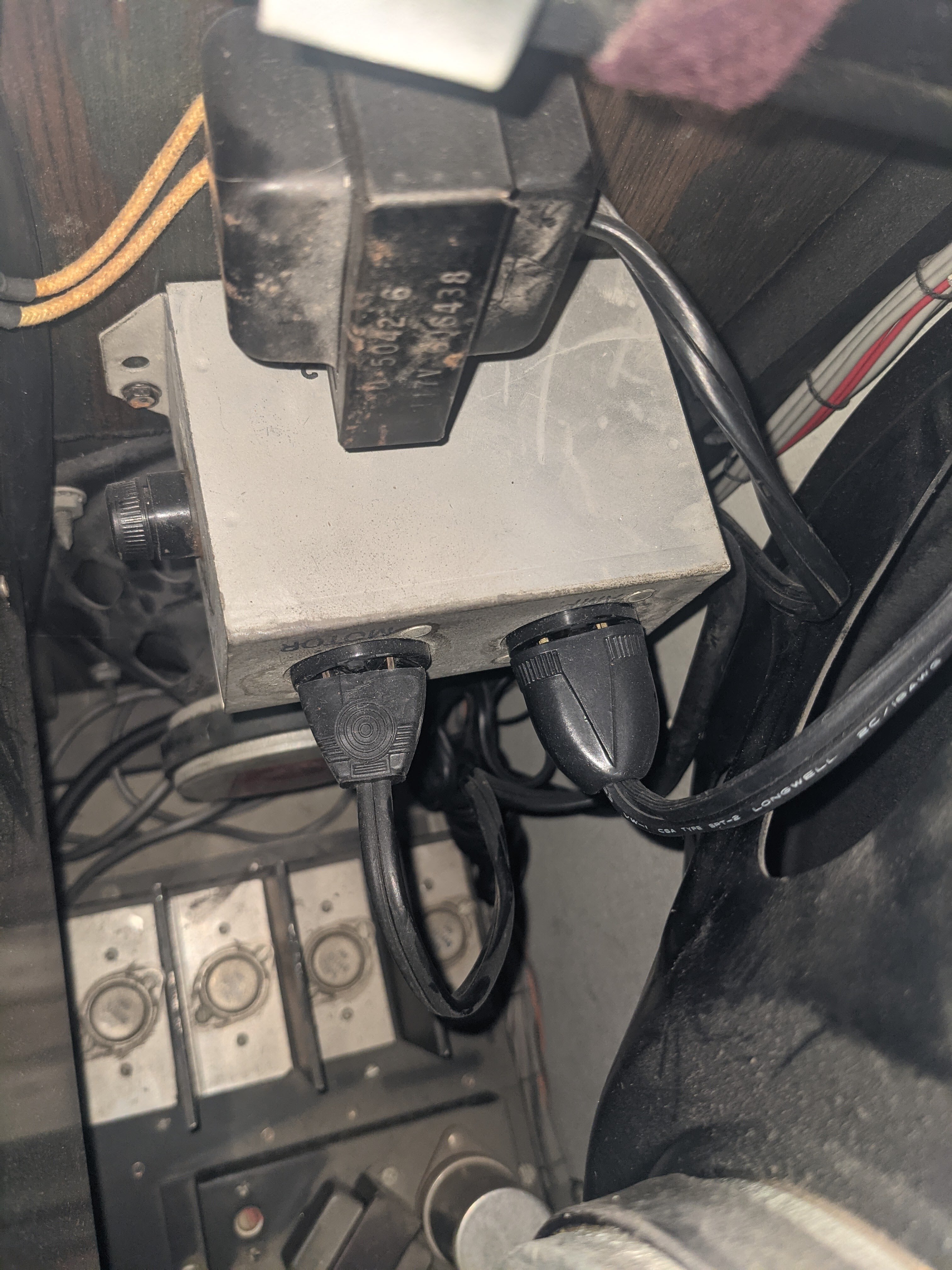
The solenoid power source is pretty much this transformer:
The reason I hesitate to use relays is because of the loud clicking sound. It might be masked by the chime sound itself, but I'd prefer not to have a chorus of clicks with each chord.
I could in theory wire up relays to that transformer, but I want to do a clean room wiring to prevent anything sketchy from happening (the organ is 50 years now). DC is way more convenient than AC, so I was looking into switching to DC.
Thanks for all the helpful questions and comments!
Almost any voltmeter has a switch or a button which must be physically turned / touched to switch between measuring DC a AC.
So from your description I'm still not sure what voltage this chime-thing uses. If there is just a transformator then it would be AC but even 50 years ago diodes where already very common to build a rectifier to create DC out of AC.
So to be sure a digital multimeter is needed and a picture that shows what measuring-configuration is actually used.
There are too many parameters in such a setup that can invert the conclusion "it must be AC"
For AC another option would be using TRIACs
Anyway this project cries for careful measurings at the beginning.
Otherwise it means re-buying components caused by destroying through quick guessings and "let's test it!"
magic sound or magic smoke ?
Actually it looks like I was measuring amperage wrong, I'll try again by putting it in the way of the current flowing instead of across the two potentials.
measuring amperage in parallel to the wires means you shortcutted the powersupply. Most Multimeters have a fuse inside for the low-ampere-area. This fuse has blown after 0,1 seconds
The 20A area has no fuse. Measuring with the 20A means you shortened the powersupply. If the powersupply is really just a transformator and you did it not too long the transformator has survived. A too long shortcutted transformator has a rather "poor" humming-sound but maybe "magic" smoke.
Interestingly everything is intact. I was reading more about my multimeter (should've done that before I tried doing anything ) and it looks like it uses an inductor in the clip to measure amperage (it only does AC). Narrowly missed that one . I'll be more careful with my equipment and high amperage electricity in the future.
You could try a test with this part that will conduct AC or DC. https://www.mouser.com/datasheet/2/196/pvt212-1732959.pdf
When used in C Connection mode, it can control up to 825mA from up to 150VAC source, and I don't know how much DC.
You only appear to need 200mA per coil, so PVT312 or PVT412 might suffice as well. (they are all 6 pin devices).
Buy a part or two from Mouser.com and do some testing.
I have a board that you can populate with 8 of them.
It's setup to drive them from a shift register. I could make a board for you with more devices, probably go with support for 32 to be more universal (4 bytes) and provide for direct drive or shift registers control.
Or just 4 of the current boards, daisy chain them, and drive with SPI.transfer:
// strike a note?
digitalWrite (ssPin, LOW);
SPI.transfer(byte0);  // one or more of the bytes contain a
SPI.transfer(byte1);  // 1 for the note being struck
SPI.transfer(byte2);
SPI.transfer(byte3);
digitalWrite (ssPin, LOW);

// hold for some time? Experiment needed

digitalWrite (ssPin, LOW);
SPI.transfer(0);  // all notes off again
SPI.transfer(0);
SPI.transfer(0);
SPI.transfer(0);
digitalWrite (ssPin, LOW);
yes you are right. your multimeter measures with the inductive principle which is secure against shortcuts.
And i knew it. all details are relevant. Without your multimeter-picture everybody would have assimed you use a non-inductive multimeter.
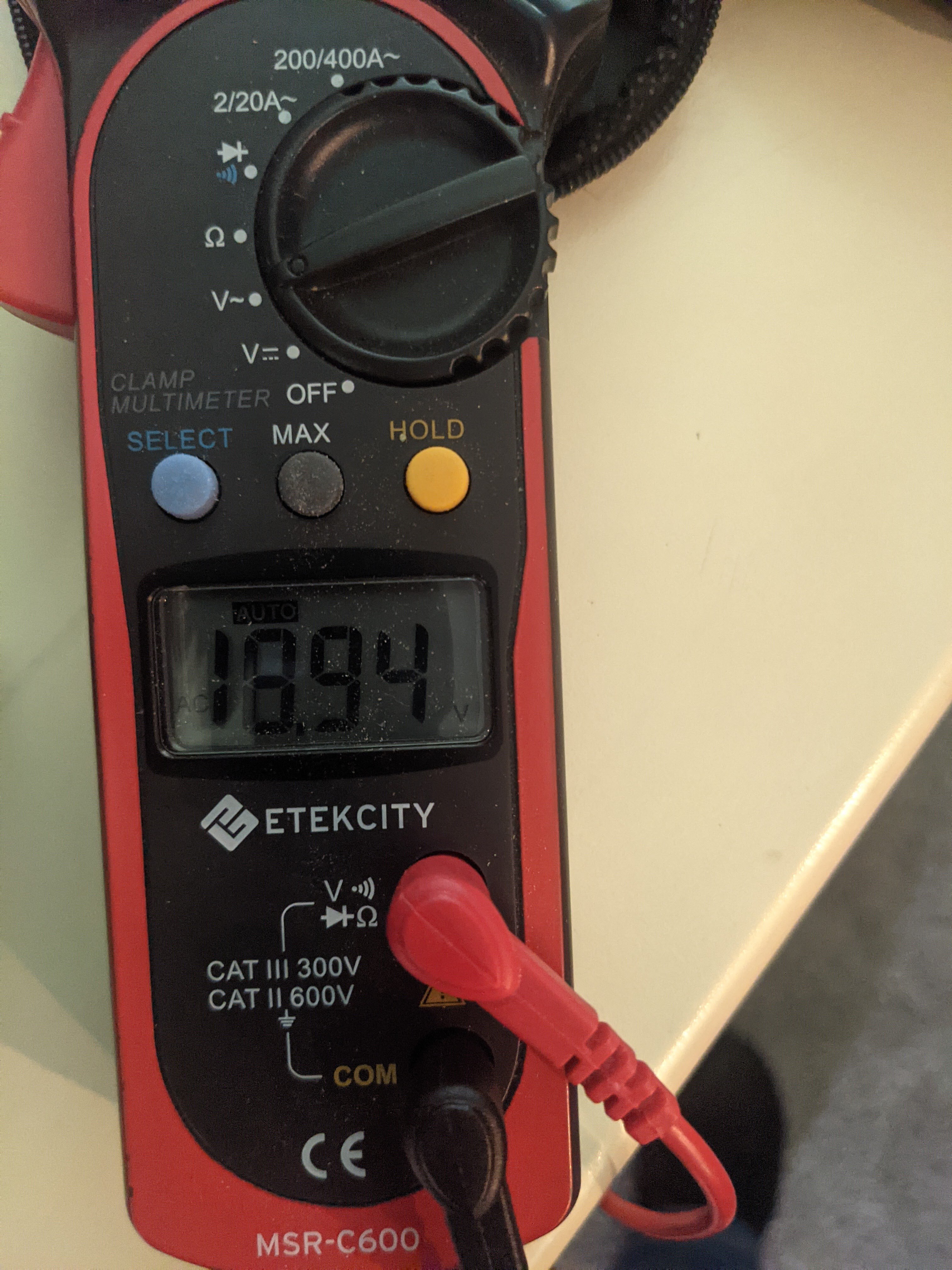
The last picture shows 2.2 A is this with solenoid switched on?
if you don,t know much about electronics yet it is a good idea to use an optocoupler stage between the microcontroller and the rest. Optocouplers transfer signals by light so there is no electrical connection. This prevents the microcontroller from high voltages.
Switching solenoids require freewheeling diodes to protect against high-voltage spikes.
From telling this you can see you need to learn about electronics and that you should let revise your plans here in the forum
The last picture is with all thirty switched on, the second one is with just one on. Using optocouplers makes sense, that'll definitely isolate the signals!
Looks like I forgot to mention this, but I'm pretty sure all the solenoids have diodes already, I'll attach a picture showing that:
I think I have a pretty good idea now of what to do, thank you!
One last question: Would it be better to use the original power source or purchase an 18 VDC power source? DC would make operating it more simple (as Arduinos tend to work better with DC).
If the powersupply is AC and the "objects" inside the drillholes are diodes this would mean the solenoids would be driven by halfwave-DC.
Then these diodes are not working as freewheeling diodes but as a simplified rectificer. Again from this you can see a deep and careful analysis of the given hardware is good.
A single solenoid switched on 0,2A all 30 switched on 2,2A is strange.
If they were all in parallel it should be 0,2A * 30 = 6A. So what is going on here?
18V is not a standardvalue for power-supplies.
standard-values are 5V, 9V, 12V 24V and of course you can buy some with 15V, 18V etc.
But as we dont know yet what is really going on I recommend buying a 24V power-supply and a DC-DC-step-down-regulator with enough amperage to drive them all.
This enables to do carefully testing beginning at low voltages to not overdrive the solenoids.
You should do further analysis to become a clear picture how it is build.
If these were diodes and work as simplified rectifier a half maybe is inserted plus minus the other half minus-plus but maybe still have a common wire and if you just switch over to DC a part might not work or you create shotcuts you shouldn't do.
Do you have access to an oscilloscope? Do you know of somebody who is near you that is an amateur-radio operator? They often have one. For a deeper analysis this would be good.
Does your school have an oscillsoscope? Is there a physics teacher who might find it interesting to see and analyse your organ?
Modern electronics are super-standardised to make them easy to use.
The microcontroller-world is not standardised. You have to take care of much more things than just "does the plug fit into the socket?"
It does appear that the devices hidden inside the wooden bar are actually diodes, clearly connected in parallel with the solenoids. These would then be "kickback" or "freewheel" diodes and you would be powering the solenoids with DC, definitely not AC.
So using the meter connected as in #10, what does it read on the DC Volts scale? This is the simplest and most obvious way to determine whether it is using AC or DC. Also, with the power off, what does it read on the Ohms (Ω) scale? Knowing the DC voltage and the actual resistance will give the current.
There are a number of "tricks" here. It is most unlikely that an organ would use AC to drive solenoids as this would tend to introduce a trembling effect. On the other hand, the supply may be rectified with a bridge rectifier but not filtered with a capacitor. This means it actually does have an AC component to it which is indicated by the clamp meter but is not linearly related to the number of solenoids actuated (and is of course, not the DC current). Now only very advanced multimeters are designed to separate the actual AC component from a voltage measurement, so an AC scale will give a significant but quite incorrect reading of a DC voltage.
What is particularly interesting is to know what device in the organ actually switches these solenoids. Presumably they are driven directly by a corresponding set of 30 of the keys in the Solo manual which each have a separate contact for the solenoids and one particular stop switches the common power to the solenoids. Since these contacts are comparatively delicate, the "kickback" diodes are quite important to prevent arcing.
Just what is the main mechanism of the organ, by the way? Just tonight on the news, there was featured the situation of someone who had just died and built their house around a Wurlitzer theatre organ!