I hope you can help me.
I have connected a torque sensor to an INA125P and a Arduino. I have connected the wires as shown in the image below.The code is below, and is just the standard example AnalogReadSerial.
My problem is, that the torque sensor is only measuring in one direction (like a load cell), but I need it to measure and output when turning it in the other direction as well.
Can you help me with the wiring? I assume I should wire the INA125P in a different way?
 /*
  AnalogReadSerial
  Reads an analog input on pin 0, prints the result to the serial monitor.
  Attach the center pin of a potentiometer to pin A0, and the outside pins to +5V and ground.

 This example code is in the public domain.
 */

// the setup routine runs once when you press reset:
void setup() {
  // initialize serial communication at 9600 bits per second:
  Serial.begin(9600);
}

// the loop routine runs over and over again forever:
void loop() {
  // read the input on analog pin 0:
  int sensorValue = analogRead(A0);
  // print out the value you read:
  Serial.println(sensorValue);
  delay(1);        // delay in between reads for stability
}
Hi Mark
Thanks for your reply.
I have just been reading about virtual grounds, but I'm a bit confused. Should I make a virtual ground with resistors or should I just connect pin 5 to a different pin on the Arduino ?
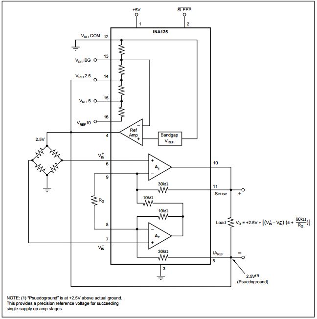
when you put 2.5 volt on the ref then output will be 2.5 volt. when -n is higher the output will be lower so negative is below2.5 volt
zero point is 512
Hi Shooter
Thanks for your reply
Sadly I´m very new, so I dont know how to put 2.5 volt on the reference..?
I think I understand the rest. From 0-512 i negative values from my sensor, and 513-1023 is positive.
My big problem is, that I dont know how to wire the setup. I have read that I might break the board if I feed the ADC a negative voltage. So I´m abit afraid of just trying.
Can you guys help with the wiring? I guess I should make a setup like the one in the image, but I dont understand where the wires should go.
With only 5volt supply on the INA, you CAN'T make 5volt or 10volt Aref.
So don't use pin 15 or pin 16.
Connect pin 4 to pin 14, so you have 2.5volt Aref.
You might have to supply the load cell from INA's ref output (pin 4).
Leo..
I want to supply the torquesensor with 10 volts...then give it a Gain 100 and get my signal. My problem is that the torque sensor give negative signal too..so I am thinking to use the voltage refernce 2.5Volt as pseudoground to get a signal like 2.5V+(signal*Gain)...
Does someone have tried it or have any idea if it will work?
Do i have to use that 2.5v as emiticion voltage to the sensor or it will work with those 10V?
Do i ground the sensor to real ground or to pseudoground?
If i use the pseudoground the emiticion voltage of sensor will be something like 10-2.5=7.5V and I should bigger the gain?
I know this is an old discussion, but in case you are looking, the attached TIFF shows a fix to the Tension compression problem with the INA125 using the 5V from an Arduino Nano (can use other Arduino boards). Basically you use a HX711 for the load cell excitation and tie the -E to the psuedogroud.