Hi All, I am doing a project using the Arduino Mega 2560 board. one of the components NRF24L01 uses the four pins,MOSI,MISO,SCK and CS. Is it possible to have a second component such as a SD shield that uses the same pins and keep them separate? Right now the NRF is using pins 50,51,52. I know there is a separate 6 pin by the reset button is also for MOSI<MISO etc. Can they both be used? Thanks for your help.
the 6 pin header is for avr programming, and probably should not be used. the pins you are referring to is called the SPI interface. its similar to i2c.

check out this page where someone did something very similar to what you are attempting.
here is the official arduion page on the spi interface. hope this helps!
Thank You! that should help
jcann9960:
I know there is a separate 6 pin by the reset button is also for MOSI<MISO etc. Can they both be used?
It is quite OK to use them, indeed it is standard practice to so. They are just a common alternative set of pins.
Nick_Pyner:
It is quite OK to use them, indeed it is standard practice to so. They are just a common alternative set of pins.
No, they are not. In the OP’s case, he said:
I know there is a separate 6 pin by the reset button is also for MOSI<MISO etc. Can they both be used?
Those are the SPI pins for the dedicated USB to serial converter atMega processor. The six pin connector to the right of the atMeag2560 processor are the duplicate pins Nick is referring to.
You can use those pins in addition to those on 50, 51 and 52 as they are connected in parallel on the pcb. The CS on pin 53 can only be connected to one device, it does not matter which one but it needs to match the software pin declaration. The second device needs its own CS pin and you can use any digital pin you desire. Again, the pin you use must appear in the object constructor in your software.
If I’ve confused you anywhere, post your code and tell us which pins you’ve used for each device, we’ll show you where to edit your software so it matches what you’ve done in hardware.
WattsThat:
No, they are not. In the OP’s case, he said:Those are the SPI pins for the dedicated USB to serial converter atMega processor.
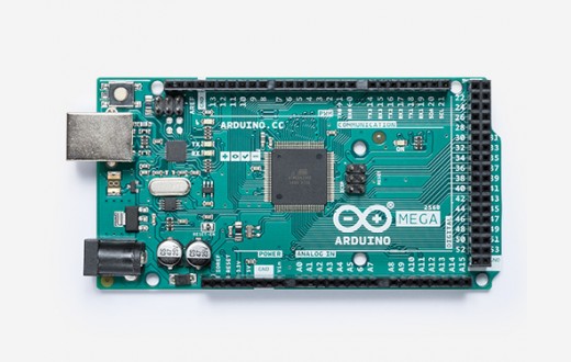
The ICSP header next to the reset button on the official Arduino Mega is the one connected to the ATmega2560:

Maybe you're thinking of some Mega derivative that has the reset button elsewhere? Or perhaps you misinterpreted what OP said? I notice in your quote you left out the preceding sentence:
jcann9960:
Right now the NRF is using pins 50,51,52. I know there is a separate 6 pin by the reset button is also for MOSI<MISO etc. Can they both be used?
From this, it seems clear to me that by "both" they mean "both pins 50,51,52 and the ICSP header next to the reset button". Perhaps you understood it as "both the ICSP header next to the ATmega16U2 and the ICSP header next to the reset button"?
WattsThat:
No, they are not. In the OP’s case, he said:
..........
If I’ve confused you anywhere,
Well it has certainly confused me, and your schematic is just that - a schematic and therefore utterly meaningless.The OP specifically referred to pins by the reset button, and that exactly describes the ICSP cluster that I was referring to. These pins are also to the right of the main chip - indeed in between that and the button. I have never known a Mega reset switch to be anywhere else and I do hope the OP does not have something weird. I guess now is the time for a photograph.
My Megas are more or less identical to the above.
Confusion is order of the day and lesson learned. There is more than one Mega configuration.
I should provided my source, this website. You cannot use the position of the reset switch to locate the header in question but the location of the header is okay since each chip has the ICSP/SPI header nearby.
I linked to the schematic strictly for the OP’s reference since it details both headers.
Well I must say that that is hell of lot better place to put the button. The (can I say) standard position is pretty dumb, and I have wondered before if it could have gone in the corner. For OP's peace of mind, the ICSP cluster is always in the same position, and I guess always clearly marked. There are heaps of pictures around that identify the individual pins.
Wow, I didn't realize they had moved the reset pin in the newest Mega boards. I stand corrected. I am accustomed to my own Megas that I bought years ago. The new position will be usable when a shield is used that covers the entire Mega. I'm surprised they made the effort, considering that the reset button is used so rarely. It made sense back in the bad old days before Arduino boards had the auto-reset circuit, but now it doesn't seem worth the extra item on the BOM. I actually thought they had done away with it altogether when I first saw that image.
