Hello everyone!
I am trying to build an aquarium controller based on the Jarduino project.
To spare you all the unneccessary details:
After using the screen and the arduino fo a few days, loading the modified codes, I started to get screen glitches.
(So, for a few days, this whole setup was working glitch free, exactly as I intended).
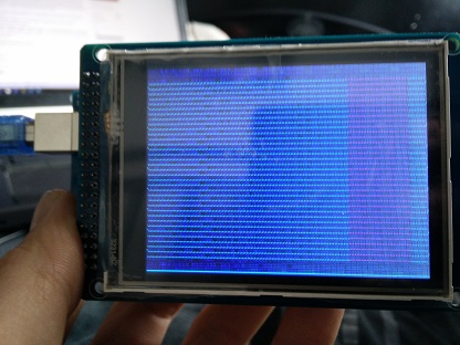
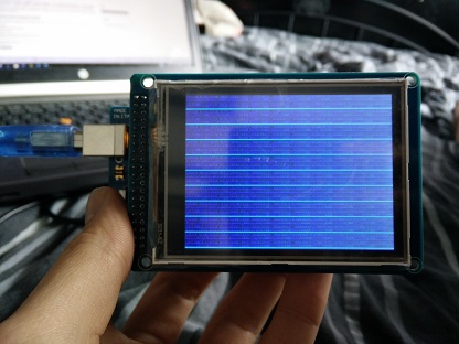
In the images attached you can see the glitches happening.
To sum up:
Materials used:
-Arduino Mega 2560
-ITDB02 v1.1 shield
-3.2" TFT from ebay with ILI9341 (16 bit parallel mode is used)
The TFT is plugged in directly into the ITDB02 shield, which is plugged in directly into the Mega.
Codes used:
-First, the Jarduino code, which gave me the glitches after a few days
-Then the examples provided by the UTFT library.
To get the ILI9341 to work, I had to mod the UTFT library, because as of now it does not support ILI9341 in 16 bit parallel mode. However, there are many threads with the solution to this. You need to modify UTFT.cpp so that the resolution of the ILI9327 entry becomes 240x320. Apart from the resolution the ILI9341 and ILI9327 work identically, or so Ive been told.
The strange part is that, once I got these glitches, they disappeared sometimes after restarting, or after having the screen glitch out for a good half hour. So it is really random when the glitches appear, but once they appear they stay on for quite some time.
Solutions tried:
-Different TFT screen
-Resoldering the ITDB02 v1.1
-Checking the ITDB02 v1.1 contacts with multimeter
-USB power
-External 9V power (yes enough amps available for the mega)
-Different library
-Clearing EEPROM
None of these solutions worked. Right now my best guess is my Arduino is broken.
However, the IDE gives no errors, and all the other sketches such as blink or the SD library work just fine.
I have already ordered a new Arduino as a sort of final solution, but do you guys know what causes these glitches? And how to fix it?
Many thanks!
ps the example sketch I used, the modded UTFT.cpp, and a few pictures of the problem are included. The colored stripes are supposed to showcase squares in different colors, but are glitching instead.
Pps. In the example sketch, I replaced
UTFT myGLCD(ITDB32S,38,39,40,41);
by
UTFT myGLCD(ILI9327,38,39,40,41);
because you need to choose your type of screen.
UTFT_Demo_320x240.ino (7.32 KB)

UTFT.cpp (27.5 KB)