I am working on the Light detector combined with op-amplifier.
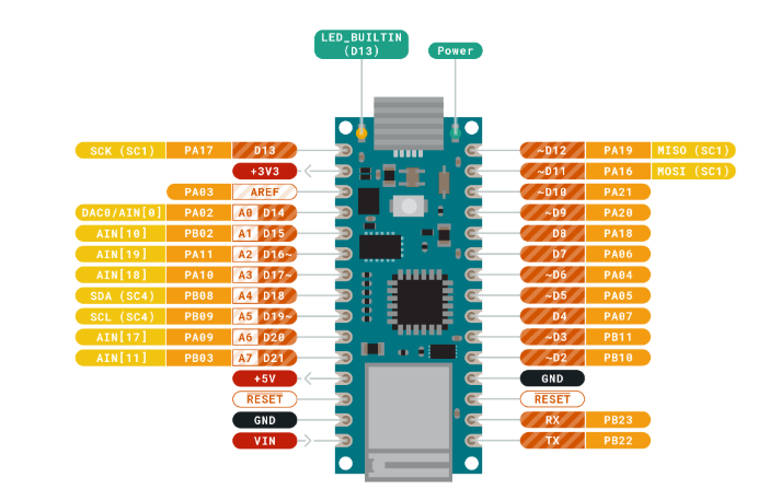
Op-AMP is AD623ANZ which has 8 pins.
(Image insert is not working)
Above is the pinout of AD623ANZ.
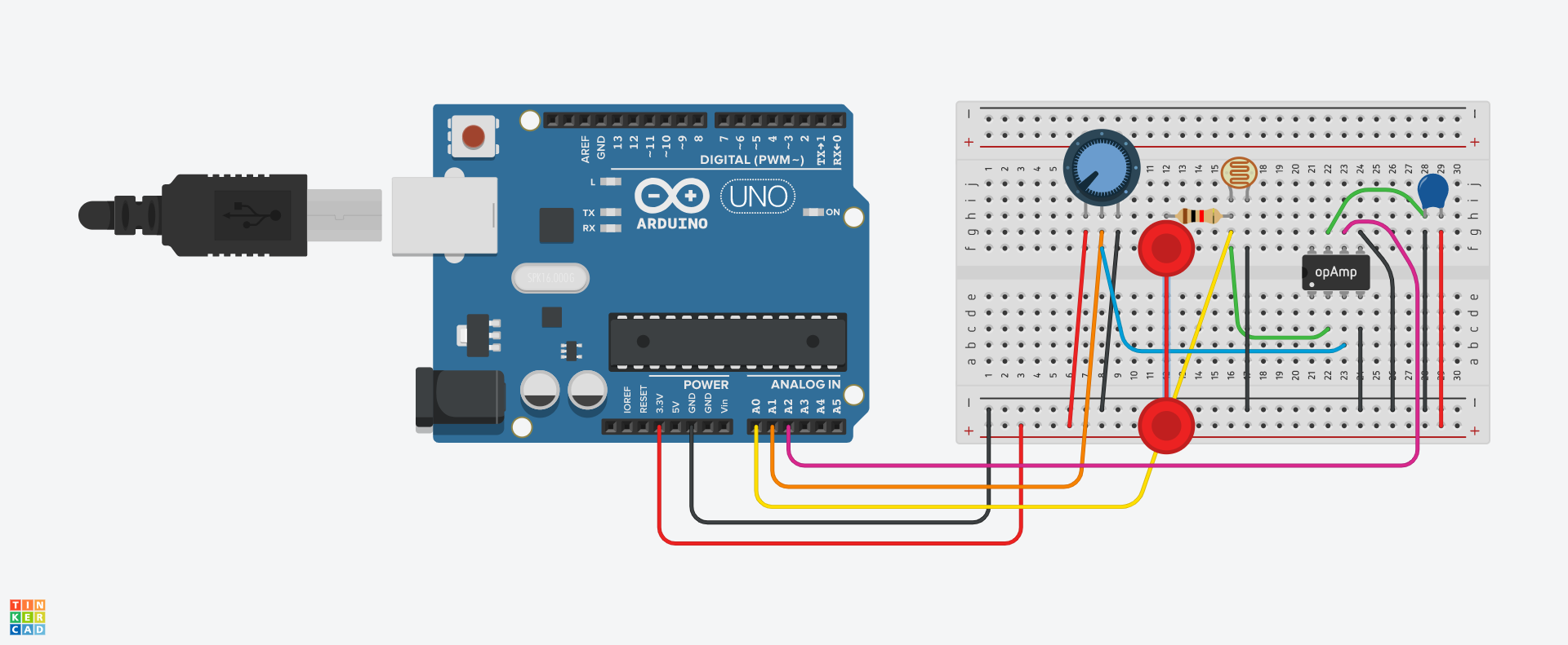
Below diagram is my full schematic of my circuit.
(Image insert is not working)
And the Arduino code I wrote down is as below.
// the setup routine runs once when you press reset:
void setup() {
 // initialize serial communication at 9600 bits per second:
 Serial.begin(9600);
}

// the loop routine runs over and over again forever:
void loop() {
 // read the input on analog pin 0:
 float sensorValue = analogRead(A0);
 float potentiometerValue = analogRead(A1);
 float amplifiedValue = analogRead(A2);
 // print out the value you read:
 Serial.print("raw value: "); // print it
 Serial.println(sensorValue);

 Serial.print("potentiometer value: "); // print it
 Serial.println(potentiometerValue);

 Serial.print("Gain is: ");
 Serial.println(amplifiedValue/(potentiometerValue-sensorValue));

 Serial.print("amplified value: "); // print it
 Serial.println(amplifiedValue);
 delay(1000);        // delay in between reads for stability
}
So basically, A0 is Vout from the photoresistor, LDR. A1 is Vout from potentiometer and A2 is Vout from the OP-AMP.
If I connect all the wires and upload the code into Arduino UNO, it perfectly reads all the signals and shows how the light detection varies along with the light condition.
However, if I only change from Arduino UNO to Arduino NANO 33 IoT, all analog inputs are oscillating and reading totally different values from Arduino UNO (I got negative gain).
(Image insert is not working)
I just hooked up Supply voltage to 3.3v pin (Second pin from left top) and ground to GND Pin (Second pin from left bottom) of Arduino Nano 33 IoT. And A0, A1, A2 respectively.
Many answers for similar problems say that it is because of common ground in the circuit.
However, I am not 100% sure what that means and how actually I can fix it.
Please read the post at the start of any forum , entitled "How to use this Forum".
OR http://forum.arduino.cc/index.php/topic,148850.0.html.
Then look down to item #7 about how to post your code.
It will be formatted in a scrolling window that makes it easier to read.
Can you please post a copy of your circuit, in CAD or a picture of a hand drawn circuit in jpg, png?
NOT a fritzy picture.
TomGeorge:
What gain do you expect from the op-amp without any feedback components?
Tom...
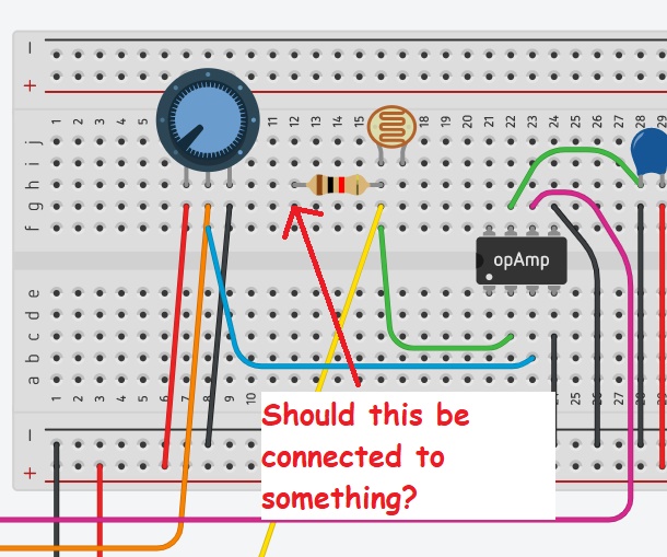
Actually, I didn't connect any resistor between OP-AMP pin 1 and 8 "yet"
Even without gain, as the Arduino Nano board cannot read the analog inputs, I did not include it.
If analog inputs circuits are not the problem, it should be something related to the voltage out and ground of arduino nano 33. Thus, more essential question to me for now is why I can power up and ground the breadboard with Arduino UNO but not with Arduino Nano 33 IoT. (Or maybe the other reason)
I have uploaded corrected schematic. Yes it should be definitely connected to the GND and Vcc
But still, I cannot insert the attached images. I do not have that icon.
TomGeorge:
Pot == Potentiometer..
See if you can read the pot with a simple bit of code.
With Arduino UNO, I can read all three analog inputs.
But with arduino Nano 33 IOT, all three inputs are oscillating. And even I change the pot, it is just fluctuating within the same range
1k pull up for the LDR is for strong sunlight.
You might not need amplification if you use the right value pull up resistor.
What are you measuring.
Seems you didn't power the op-amp (+Vs is grounded),
and you did leave gain at 1x (no resistor, no amplification).
But Fritzing is toddler art, and usually misleading in the hands of a beginner.
Learn to draw real circuit diagrams, with pencil and paper.
Did you look at the input common mode ranges at 3.3volt supply.
The LDR/amplifier might not do what you hope it will do.
Leo..