Arduino Nano, ADC, Multiple Inputs, Unreliable Measurements
Hello, this is my first time ever posting, so I'm ready for an influx of feedback on what I forgot to include in my posts. Thank you for understanding!
I have been debugging this for cumulative hours now, and this is one of those annoying issues that seem unexplainable and irritating... like it shouldn't even be possible. That probably means there is some confounding element I have not considered yet and is my hope to find out by posting this.
Final Goal: Use an Arduino nano to implement Great Scott’s Arduino-based digital electronic load build, eventually as one building block to build my Solar Cell maximum power point locator device.
His video: LINK
His schematic at 7:53 will be the eventual goal (and I already have a prototype soldered for that exact schematic), but is not the schematic involved in this issue.
Current Goal: Fix an issue with the Arduino seemingly unable to read two consecutive analog inputs in rapid succession.
Circuit Schematic:

Circuit prototype:


Arduino program:
// October 7, 2023

#define pwm   9
#define sensCur_Pin A4
#define sensVol_Pin A1

// Constants
const bool enableSerialDebug =  false;   // choose to print every measurement
const float setPower_W =        0.50;
const int serialBaudRate =      9600;
const int loopRefresh_ms =      250;

int counter = 0;

// Power Electronics - Constants
const int PWMrange_topVal =       2047;
const float nominalArd_5V_Val =   5.0;
const float coef_VPinToVCC =      1;        // Undoes voltage divider conversion
const float currSens_min_A =      0.16;
const float ACS712_30A_Vstep =    0.066;
const unsigned char PS_128 =      (1 << ADPS2) | (1 << ADPS1) | (1 << ADPS0);

// Power Electronics - Variables
int currSens_Pin_ADC =    0;
int volSens_Pin_ADC =     0;

float ACS712_offset =     0;
float currSens_Pin_V =    0;
float currSens_I_A =      0;
float currSens_I_mA = 0;

float volSens_Pin_V =     0;
float volSens_VCC_V =     0;
float measPower_W =       0;


void setup()
{
  ACS712_offset = nominalArd_5V_Val / 2;

  // Start processes
  Serial.begin(serialBaudRate);

  // Set pins
  pinMode(sensCur_Pin, INPUT);          // Analog ACS712 I Sense IC output
  pinMode(sensVol_Pin, INPUT);          // Analog ACS712 I Sense IC output

  pinMode(pwm, OUTPUT);                 // PWM mosfet drive signal
  digitalWrite(pwm, LOW);               // PWM mosfet drive signal

  // Configure registers and timers
  ADCSRA &= ~PS_128;
  ADCSRA |= (1 << ADPS1) | (1 << ADPS0);
  PCICR |= 0b00000100;
  PCMSK2 |= 0b00010000;   // turn o PCINT20(D4)

  TCCR1A = 0;
  TCCR1A = (1 << COM1A1) | (1 << WGM11);
  TCCR1B = 0;
  TCCR1B = (1 << WGM13) | (1 << WGM12) | (1 << CS10);
  ICR1 = PWMrange_topVal;
  OCR1A = 1450;

  Serial.println(" ");
  Serial.println("STARTING");
}


void loop()
{
  // Sense Current from Supply
  currSens_Pin_ADC = analogRead(sensCur_Pin);
  currSens_Pin_V = currSens_Pin_ADC * (5.00 / 1023.00);
  currSens_I_A = (currSens_Pin_V - ACS712_offset) / ACS712_30A_Vstep;
  if (currSens_I_A < currSens_min_A) currSens_I_A = 0;
  currSens_I_mA = currSens_I_A * 1000.0;

  // Sense Voltage from Supply
  volSens_Pin_ADC = analogRead(sensVol_Pin);
  volSens_Pin_V = volSens_Pin_ADC * (5.00 / 1023.00);
  volSens_VCC_V = volSens_Pin_V * coef_VPinToVCC;

  /*Serial.print("measI_ADC: ");
  Serial.print(currSens_Pin_ADC);
  Serial.print(" | measI_V: ");
  Serial.print(currSens_Pin_V, 3);*/
  Serial.print("| measI_mA: ");
  Serial.print(currSens_I_mA, 1);
  Serial.print(" | measV_V: ");
  Serial.println(volSens_VCC_V);

  // Power Calculation
  measPower_W = volSens_VCC_V * currSens_I_A;

  /*
  if(enableSerialDebug)
  {
    Serial.print("setW: ");
    Serial.print(setPower_W);
    Serial.print(" --- ");
    Serial.print("measI: ");
    Serial.print(currSens_I_A);
    Serial.print(" | measV: ");
    Serial.print(volSens_VCC_V);
    Serial.print(" | measW: ");
    Serial.print(measPower_W);
    Serial.print(" --- ");
  }

  // Regulate V_G to increase or decrease power across FET
  if (measPower_W < setPower_W)
  {
    OCR1A++;
    if(OCR1A >= PWMrange_topVal)  // Disallow exceeding 100% duty cycle
      OCR1A = PWMrange_topVal;
  }
  else
  {
    if(OCR1A == 0) OCR1A = 0;     // Disallow reverse overflow
    else OCR1A = OCR1A - 1;
  }

  if(enableSerialDebug)
  {
    Serial.print("OCR1A:");
    Serial.println(OCR1A);
  }
*/
  delay(loopRefresh_ms);
}
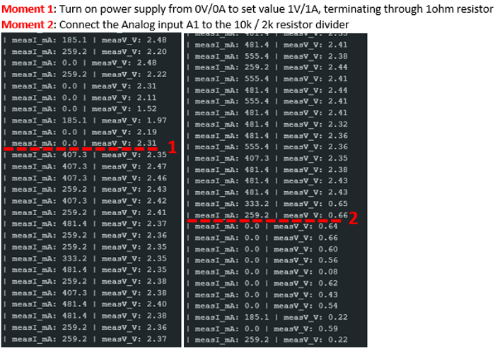
Observed Behavior:
Other materials already consulted:
Source 1: LINK
- Check Breadboard for continuous connections to analog signals
- Check that Arduino pins are soldered and don’t have any dry joints
Source 2: LINK - Check that AREF pin is not shorted to any neighboring pins or ground
- Just try a second Arduino to see if results stay the same with the same circuit / code
Source 3: LINK - In firmware, discard readings of other analog inputs. The pins can have some residual voltage which influence the behavior of other analog pins.
Source 4: LINK - Reading multiple inputs in quick succession is an issue only if there is high input impedance and if there is a significant difference in the analog level of the different pins – causing the slew rate to be an impacting factor
Source 5: LINK - Source impedance for A0-5 pins
- Ways to control / limit input impedance using RC circuits and op amps
Suspected Issues:
- Little 1 Ohm resistor termination to observe 1:1 current from supply to current measurement module is a big no no, even if I only turn the supply on for 10 seconds maximum to observe serial monitor output, for reasons of heat dissipation and too low of impedance.
- Issues with ADC "slew" rate and low times between "polls", not allowing for the voltage to change fast enough on the pins.
The rest is beyond me. I have no clue why connecting one analog pin to GND would cause a different, previously properly functioning pin to start measuring completely inaccurately.