I completed task #49
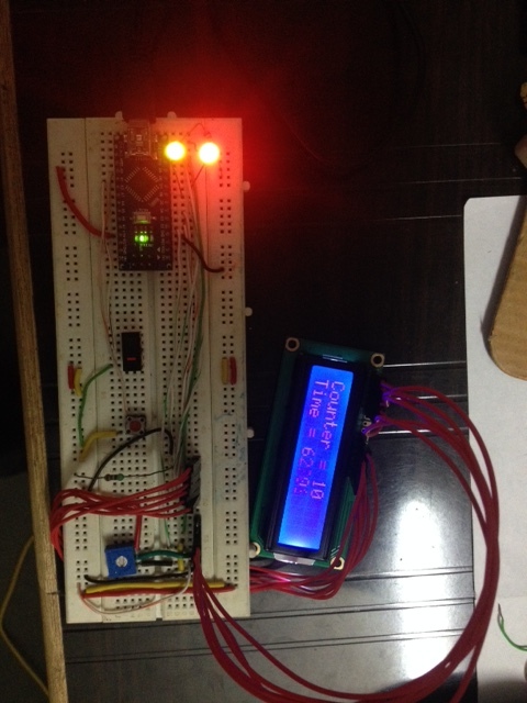
I connect LCD as per your instruction, but that LCD having some problem. so i connect LCD outside.
- one was NAME display
- One was Counter
- Last one was timer.
I completed task #49
I connect LCD as per your instruction, but that LCD having some problem. so i connect LCD outside.
Hi,
Double check your wiring to the LCD around pins 4, 5, and6.
Can you post a better picture of your LCD connections, that is from above.
Thanks Tom.. ![]()
Hi,
I checked that LCD was ok but during un-soldering some track was open that why it was not display.
no problem i connect new LCD and it was working.
You are doing well!
Edit
11. Make a change to your sketch so the screen is updated only once every 3 seconds.
12. Do the Increment and Decrement switches work the same as before?
Why or why not?
13. What happens with the two LEDs when buttons are pushed?
(is there one 220 ohm resistor for each LED?)
.
Please read this web page.
Do not change the wiring on your breadboard until requested to do so.
When you are finished reading that page let us know.
How would you change the sketch so negative numbers are displayed?
example: Counter = -1
-NO
What do you have to change in the sketch to make the Increment switch add 10 each time you
push it?
*** Tutorial – Using DS1307 and DS3231 Real-time Clock Modules with Arduino ***
What has to be changed in the sketch?
===============
Make a change to your sketch so the screen is updated only once every 3 seconds.
Do the Increment and Decrement switches work the same as before?
Why or why not?
What happens with the two LEDs when buttons are pushed?
Is there a 220 ohm resistor in series with each each of your LEDs?
======================
delay(2000); //wait here for 2000 milli seconds, 2 seconds
I want to see 10,20,30 . . .
What has to change in the sketch to get this to happen?
===============
Good!
delay(2000); //wait here for 2000 milli seconds, 2 seconds
Yes
Or use
int
or
long
CounterValue = CounterValue + 10;
I want to see 10,20,30 . . .
What has to change in the sketch to get this to happen?
===============
delay(3000) Freezes the Arduino for this delay period.
Therefore, the switches are not read and the program slows.
We will see a way to fix this later.

Use the new sketch in Post # 104
//Sketch_02
//Date and time functions using a DS1307 RTC connected via I2C (A4/A5) using Wire lib
//RTC used is the DS1307
//To make your sketch more readable, format your code every now and then. Press CTRL T
//Get the RTClib library from here:
// https://github.com/adafruit/RTClib
//Install the library in C:\Users\YourName\Documents\Arduino\libraries\
//You should then have this entry: C:\Users\YourName\Documents\Arduino\libraries\RTClib
//You must restart all open IDEs after library installation
#include <Wire.h> //This is needed to talk to the RTC
#include <LiquidCrystal.h> //include the LCD library in this Sketch
#include "RTClib.h" //This helps you write/read data to/from the RTC
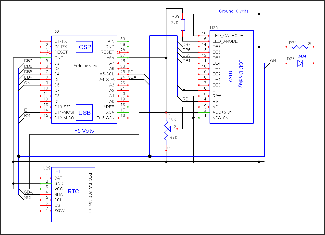
LiquidCrystal lcd(12, 11, 5, 4, 3, 2);
RTC_DS1307 RTC;
// Define variables
DateTime now;
const byte ONLED = 6; //the ON LED is connected to this pin
//**********************************************************************
void setup ()
{
//baud rate for the serial port
Serial.begin(9600);
//number of columns and rows for this LCD
//this is a 16 character by 2 row LCD
lcd.begin(16, 2);
//start the RTC
Wire.begin();
RTC.begin();
pinMode(ONLED, OUTPUT); //On LED connected here
//clear the LCD screen, LCD cursor to location 0,0
lcd.clear();
//0,0 is the first character on the first line on the LCD
// 0000000001111111 column position
// 0123456789012345
lcd.print("Hi patelhiren!!!");
delay(3000);
//check to see if the RTC is working
if (!RTC.isrunning())
{
lcd.print("RTC is not working");
//Serial.println("RTC is NOT running!");
}
// Set the RTC time
// Get the current time fron the PC, send the time to the RTC
// After setting the RTC time, comment the next line and upload this sketch to the Nano again
//RTC.adjust(DateTime(__DATE__, __TIME__));
} // >>>>>>>>>>>>>> E N D O F s e t u p ( ) <<<<<<<<<<<<<<<<<
//**********************************************************************
void loop ()
{
delay(500);
//read the time from the RTC
now = RTC.now();
//Toggle the ON LED every second
//is the current second an even number?
if(now.second()%2 == 0)
{
digitalWrite(ONLED, HIGH); //LED is ON for even seconds
}
else
{
digitalWrite(ONLED, LOW); //LED is OFF for odd seconds
}
//update the date and time LCD display
printLCDtime();
// If you want date and time send to the serial monitor, remove the // from the follow 12 lines
//Serial.print(now.year(), DEC);
//Serial.print('/');
//Serial.print(now.month(), DEC);
//Serial.print('/');
//Serial.print(now.day(), DEC);
//Serial.print(' ');
//Serial.print(now.hour(), DEC);
//Serial.print(':');
//Serial.print(now.minute(), DEC);
//Serial.print(':');
//Serial.print(now.second(), DEC);
//Serial.println();
} // >>>>>>>>>>>>>> E N D O F l o o p ( ) <<<<<<<<<<<<<<<<<
//======================================================================
// F U N C T I O N S
//======================================================================
//**********************************************************************
//Function to send date and time to the LCD
void printLCDtime()
{
//clear the LCD screen, LCD cursor to location 0,0
lcd.clear();
// 0000000001111111
// 0123456789012345
// YYYY/MM/DD
lcd.print(now.year(), DEC);
lcd.print("/");
printDigits(now.month());
lcd.print("/");
printDigits(now.day());
//move the LCD cursor to the first character on the second line
lcd.setCursor(0,1);
// 0000000001111111
// 0123456789012345
// HH:MM:SS
printDigits(now.hour());
lcd.print(":");
printDigits(now.minute());
lcd.print(":");
printDigits(now.second());
} // END of printLCDtime()
//**********************************************************************
//Function to print leading 0s
void printDigits(int digits)
{
if(digits < 10)
{
//add a leading zero to numbers i.e. 0-9 = 00-09
lcd.print('0');
}
lcd.print(digits);
} //END of printDigits()
//======================================================================
// E N D O F C O D E
//======================================================================
RTClibrary.zip (13.8 KB)
Were you able to get the RTC circuit and the sketch to work?
.
ok,
I will search in google
This one is ok?

"This one is ok?"
You told us you had this RTC, use it:

.
Ya, i purchase online but, it will take time.
The RTC shown in post #96 should work.
The best RTC I have used this is the DS3231.
They are much superior, more accurate, than the DS1307.
The DS3231 is about $2.00 each.
example:
I do not believe the Dallas RTC will work in this application.
.