If you want to be serious in this project use the DS3231.

.
ok,
i will purchase DS3231 (RTC)
The first time you run the sketch, uncomment this line:
//RTC.adjust(DateTime(DATE, TIME));
This gets the date and time from the PC at the moment you upload the sketch and sets the RTC time
The next and subsequent times you download the sketch, make sure the line is commented again.
-???
You only do #5 once : RTC.adjust(DateTime(DATE, TIME));
From then on, you use //: //RTC.adjust(DateTime(DATE, TIME));
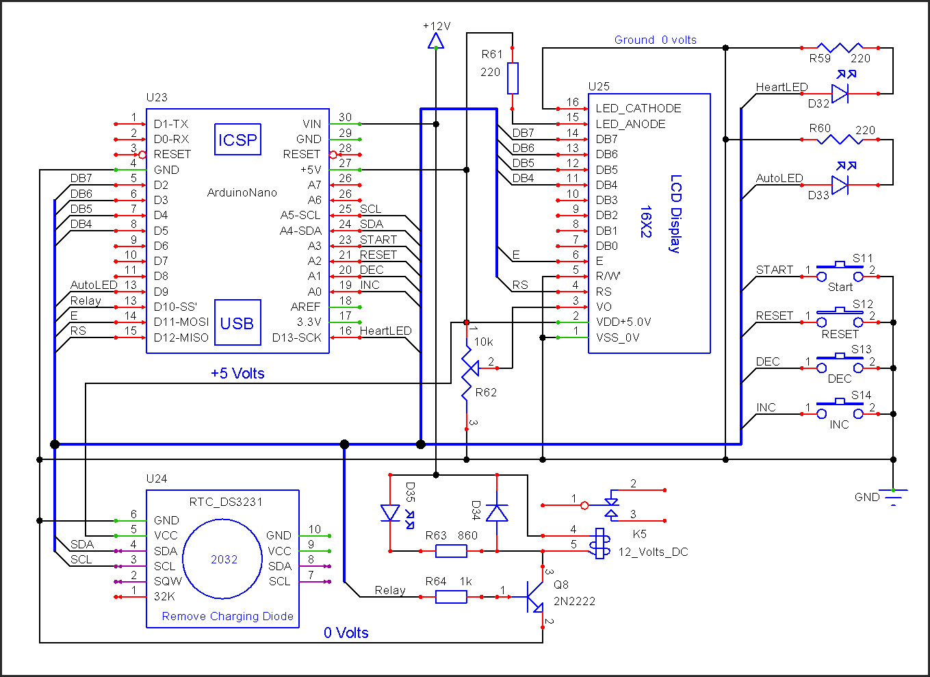
New schematic with the DS3231 RTC:
New sketch that does not need the 3rd party RTC library:
//Sketch_02

// N O T E :     No third party libraries are required with this sketch

//Date and time functions using a RTC connected via I2C (A4/A5) using Wire lib
//RTC used is the DS3231 or DS1307

//To make your sketch more readable, format your code every now and then. Press CTRL T

#include <Wire.h>                //Used with the RTC
#define DS3231_I2C_ADDRESS 0x68  //I2C address of the RTC

#include <LiquidCrystal.h>       //LCD library
//      LCD pins:  RS   E DB4 DB5 DB6 DB7
LiquidCrystal lcd( 12, 11,  5,  4,  3,  2); //Arduino

//Define Global variables
const byte ONLED = 6; //the ON LED is connected to this pin
byte second, minute, hour, dayOfWeek, dayOfMonth, month, year;

//**********************************************************************
void setup ()
{
  //baud rate for the serial port
  Serial.begin(9600);

  pinMode(ONLED, OUTPUT); //On LED connected here

  //start up the RTC communications
  Wire.begin();
  //To set the RTC time:
  //uncomment the third line down, as needed make changes to: SS,MM,HH,DD,DT,MM,YY
  //upload this sketch, comment the line again, upload this sketch again!!!
  //DS3231         SS,MM,HH,DD,DT,MM,YY
  //setDS3231time ( 0,57,16, 4,20, 4,16); //uncomment to set the RTC time

  //number of columns and rows for this LCD
  //this is a 16 character by 2 row LCD
  lcd.begin(16, 2);

  //clear the LCD screen, LCD cursor to location 0,0
  lcd.clear();

  //0,0 is the first character on the first line on the LCD
  //         0000000001111111  column position
  //         0123456789012345
  lcd.print("Hi patelhiren!!!");
  delay(3000);

} //  >>>>>>>>>>>>>> E N D  O F  s e t u p ( ) <<<<<<<<<<<<<<<<<

//**********************************************************************
void loop ()
{
  delay(1000);   //this will be removed and replaced with a BWD routine
  displayTime(); //display the date and time on the LCD and serial monitor

  //**************************************
  //toggle the ON LED every second
  //is the current second an even number?
  if(second % 2 == 0)
  {
    digitalWrite(ONLED, HIGH); //LED is ON for even seconds
  }
  else
  {
    digitalWrite(ONLED, LOW);  //LED is OFF for odd seconds
  }
  //**************************************

  //              Other loop() code goes here


} //  >>>>>>>>>>>>>> E N D  O F  l o o p ( ) <<<<<<<<<<<<<<<<<

//======================================================================
//                      F U N C T I O N S
//======================================================================


//**********************************************************************
//Function to print leading 0s
void printDigits(int digits)
{
  if(digits < 10)
  {
    //add a leading zero to numbers i.e. 0-9 = 00-09
    lcd.print('0');
  }

  lcd.print(digits);

} //END of printDigits()

//**********************************************************************
//Function to convert normal decimal numbers to binary coded decimal BCD
byte decToBcd(byte val)
{
  return( (val/10*16) + (val%10) );
} //END of decToDcb()

//**********************************************************************
//Function to convert binary coded decimal BCD to normal decimal numbers
byte bcdToDec(byte val)
{
  return( (val/16*10) + (val%16) );
} //END of bcdToDec()

//**********************************************************************
//Function to set the time on the RTC
void setDS3231time(byte second, byte minute, byte hour, byte dayOfWeek, byte
dayOfMonth, byte month, byte year)
{
  // sets time and date data to DS3231
  Wire.beginTransmission(DS3231_I2C_ADDRESS);
  Wire.write(0); // set next input to start at the seconds register
  Wire.write(decToBcd(second));     // set seconds
  Wire.write(decToBcd(minute));     // set minutes
  Wire.write(decToBcd(hour));       // set hours
  Wire.write(decToBcd(dayOfWeek));  // set day of week (1=Sunday, 7=Saturday)
  Wire.write(decToBcd(dayOfMonth)); // set date (1 to 31)
  Wire.write(decToBcd(month));      // set month
  Wire.write(decToBcd(year));       // set year (0 to 99)
  Wire.endTransmission();
} //END of setDS3231time()

//**********************************************************************
//Function to read the time and date form the RTC
void readDS3231time(byte *second,byte *minute,byte *hour,byte *dayOfWeek,byte *dayOfMonth,byte *month,byte *year)
{
  Wire.beginTransmission(DS3231_I2C_ADDRESS);
  Wire.write(0); // set DS3231 register pointer to 00h
  Wire.endTransmission();
  Wire.requestFrom(DS3231_I2C_ADDRESS, 7);
  // request seven bytes of data from DS3231 starting from register 00h
  *second = bcdToDec(Wire.read() & 0x7f);
  *minute = bcdToDec(Wire.read());
  *hour = bcdToDec(Wire.read() & 0x3f);
  *dayOfWeek = bcdToDec(Wire.read());
  *dayOfMonth = bcdToDec(Wire.read());
  *month = bcdToDec(Wire.read());
  *year = bcdToDec(Wire.read());
}

//**********************************************************************
//Function to send the date and time to the LCD and the Serial Monitor
void displayTime()
{
  // retrieve data from DS3231
  readDS3231time(&second, &minute, &hour, &dayOfWeek, &dayOfMonth, &month,
  &year);

  //*******************************************
  //clear the LCD screen, LCD cursor to location 0,0
  lcd.clear();

  //send YY/MO/DD to the LCD
  //        0000000001111111
  //        0123456789012345
  //        YY/MO/DD
  lcd.print(year, DEC);
  lcd.print("/");
  printDigits(month);
  lcd.print("/");
  printDigits(dayOfMonth);

  //*******************************************
  //move the LCD cursor to the first character on the second line
  lcd.setCursor(0,1);

  //send HH/MI/SS to the LCD
  //          0000000001111111
  //          0123456789012345
  //          HH:MI:SS
  printDigits(hour);
  lcd.print(":");
  printDigits(minute);
  lcd.print(":");
  printDigits(second);

  //*******************************************
  Serial.print(hour, DEC);
  // convert the byte variable to a decimal number when displayed
  Serial.print(":");
  if (minute < 10)
  {
    Serial.print("0");
  }
  Serial.print(minute, DEC);
  Serial.print(":");
  if (second < 10)
  {
    Serial.print("0");
  }
  Serial.print(second, DEC);
  Serial.print(" ");
  Serial.print(dayOfMonth, DEC);
  Serial.print("/");
  Serial.print(month, DEC);
  Serial.print("/");
  Serial.println(year, DEC);

  //*******************************************

} //END of displayTime()


//======================================================================
//                      E N D  O F  C O D E
//======================================================================
In your post #27
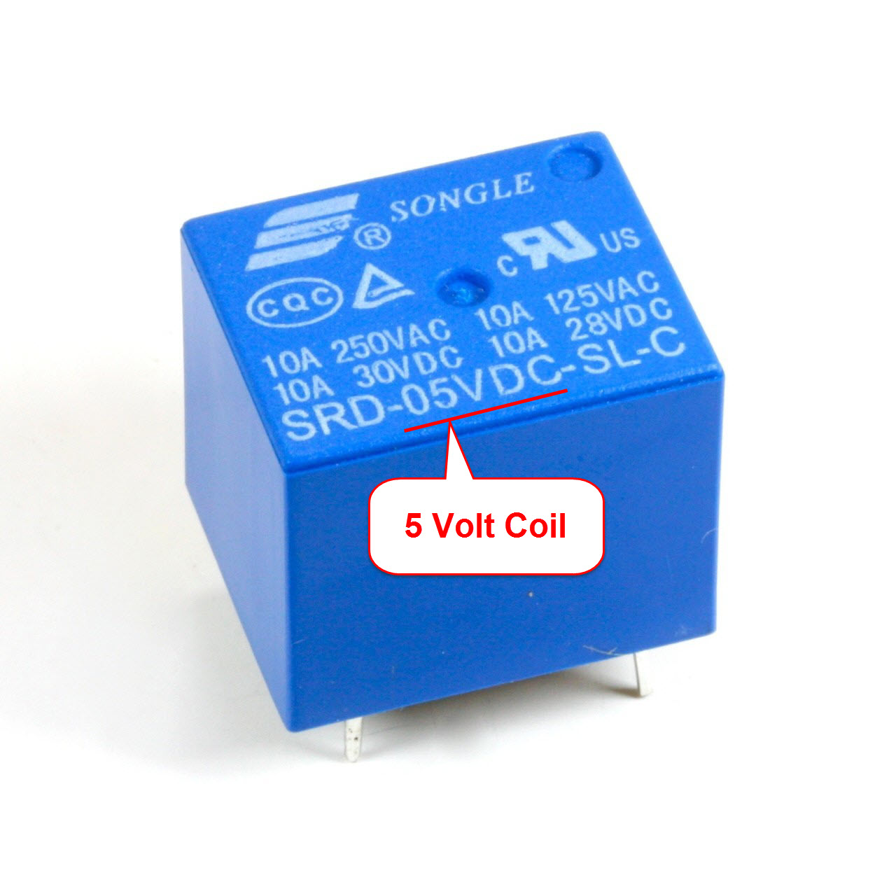
I want to operate one relay (12V)
You said you want to operate a 12 volt relay but the image you showed us has a 5 volt coil.
What relay do you have?
LarryD, you deserve a medal for perseverance. +1 karma.
I assume you like a challenge!
Weedpharma
One good deed per year ![]()
While you wait to get your RTC.
Assumptions
Are the assumptions correct?
What is the function of “Reset” switch?
What is the function of “Start” switch?
What exactly is the relay going to control?
If the power fails, what mode is the clock to be in when the power comes back on?
Both relay, i have 5V and 12V, i use 12V relay.
*** I will use the increment and decrement switches to set the relay OFF time, example 5:00PM.
** When i press auto/manual switch, LED shown timer in auto or manual mode, (If, led ON means timer in auto mode and LED OFF means timer in manual mode)
*** In auto mode timer will work as per set ON-OFF timing and in manual mode timer will ON relay directly.
-NA
Are the assumptions correct?
What is the function of "Reset" switch?
I try this
CounterValue++; //increment the counter value
CounterValue+10; //increment the counter value
and ti was working
But
CounterValue--;
CounterValue-10; or any other command ???
it was not working
I try this
CounterValue++; //increment the counter value
CounterValue+10; //increment the counter value
CounterValue = CounterValue + 10;
and ti was working
But
CounterValue--;
CounterValue-10; or any other command ???
CounterValue = CounterValue - 10;
it was not working
Both relay, i have 5V and 12V, i use 12V relay.
** When i press auto/manual switch, LED shown timer in auto or manual mode, (If, led ON means timer in auto mode and LED OFF means timer in manual mode)
*** In auto mode timer will work as per set ON-OFF timing and in manual mode timer will ON relay directly.
So the LED can be called the: AutoLED
When the LED is turned on you are in: Automatic.
When the LED is turned off you are in: Manual
What is the function of "Reset" switch?
What is the function of "Start" switch?
What exactly is the relay going to control?
If the power fails, what mode is the clock to be in when the power comes back on?
Edit:
NEW SCHEMATIC
CounterValue = CounterValue + 10;
CounterValue = CounterValue - 10;
ok, i try both are working ...
** When i press auto/manual switch, LED shown timer in auto or manual mode, (If, led ON means timer in auto mode and LED OFF means timer in manual mode)
*** In auto mode timer will work as per set ON-OFF timing and in manual mode timer will ON relay directly.
So the LED can be called the: Auto LED
When the LED is turned on you are in: Automatic.
When the LED is turned off you are in: Manual
What is the function of "Reset" switch?
For set time
Set the time the relay turns off.
Yes
What is the function of "Start" switch?
For set time
Set the time the relay turns on.
Yes
What exactly is the relay going to control?
Relay working depend on ON-OFF time, when set ON time match with clock time relay will ON, and when set OFF time will match with clock time relay will OFF.
What kind of device will the relay be connected to?
Automatic Valve (Water)
Water pump
//********************************************
#include <LiquidCrystal.h> // not-under stand?
const byte IncSwitch = 14;
const byte DecSwitch = 15;
const byte ONLED = 6;
const byte OFFLED = 7;
byte LastIncSwitch = LOW;
byte LastDecSwitch = LOW;
byte CounterValue = 0;
LiquidCrystal lcd(12, 11, 5, 4, 3, 2);
// this is a Inputs, Outputs, Memory storage location and LCD configuration!!!
// and this is a initially stage of programme
//**********************************************
I under stand correctly?
//**********************************************
void setup() { // Don't under stand
pinMode(IncSwitch, INPUT_PULLUP);
pinMode(DecSwitch, INPUT_PULLUP);
pinMode(ONLED, OUTPUT);
digitalWrite(ONLED, HIGH);
pinMode(OFFLED, OUTPUT);
digitalWrite(OFFLED, HIGH);
lcd.begin(16, 2);
lcd.clear();
lcd.print("Arduino NANO");
delay(5000);
lcdDisplay();
}
//>>>>>>>>>>>>>> E N D O F s e t u p ( ) <<<<<<<<<<<<<<<<<
Here input - output and LCD set-up and LCD printing.
I under stand correctly?
//*****************************************************
//F U N C T I O N S
void lcdDisplay()
{
lcd.clear();
lcd.setCursor(0,0);
lcd.print("Counter = ");
lcd.print(CounterValue);
lcd.setCursor(0,1);
lcd.print("Time = ");
lcd.print(millis());
}
// E N D O F C O D E
//***********************************************************
this is for counter display and timer display
//********************************************
#include <LiquidCrystal.h> // not-under stand?
Someone has written code and put it in a file called LiquidCrystal.h
"Include" says, a library called LiquidCrystal must be included in this sketch
You need this library so you can send data to the LCD.
You can find the library in:
C:\Program Files (x86)\arduino-1.0.6-windows\arduino-1.0.6\libraries\LiquidCrystal
const byte IncSwitch = 14;
'const' is the same as "constant".
A constant variable cannot be changed.
Constant variables do not need any SRAM where as a 'byte' needs 1 byte, 'int' needs 2 bytes, etc.
const byte DecSwitch = 15;
const byte ONLED = 6;
const byte OFFLED = 7;
byte LastIncSwitch = LOW;
byte is used here because you want to be able to change the variable in the sketch.
If you were to use const you would get an error.
byte LastDecSwitch = LOW;
byte CounterValue = 0;
LiquidCrystal lcd(12, 11, 5, 4, 3, 2);
This tells the sketch which pins to use to talk to the LCD display.
You should go back to my previous posts where I gave links to programming pages that you should read.
//**********************************************
void setup() { // Don't under stand
You need at least 2 functions in a sketch.
void setup() and void loop() are the 2 functions needed
'void' means this function returns no information to code that 'calls' it.
The function void setup() is run first and only at power up.
If you have things that need initialization when power is turned on, you put that code in setup()
The function void loop() runs after setup().
loop() is restarted as soon as the loop() ends.
pinMode(IncSwitch, INPUT_PULLUP);
The switch connected to IncSwitch is an input and its internal 20-50k resistor is connected to +5V
pinMode(DecSwitch, INPUT_PULLUP);
pinMode(ONLED, OUTPUT);
The output pin called ONLED is set to be an output pin.
digitalWrite(ONLED, HIGH);
Send a HIGH to ONLED
pinMode(OFFLED, OUTPUT);
digitalWrite(OFFLED, HIGH);
Here input - output and LCD set-up and LCD printing.
I under stand correctly?
Yes