I have two questions here...
I built the arduino on a breadboard as described on this website (atmega328p-pu, serial connection using a FT232RL USB module on RX/TX pins with 10k pullup, DTR connection through 104 ceramic capacitor to reset pin along with another pullup) and serial communication is messed up. I can still upload sketches using the manual reset AND I can send serial data using the same method, but if the atmega is already powered on for some time (ie. 3-4 seconds or so) I simply cannot communicate with it at all. So my question is: any idea on what I could try/what could be wrong (I always get the out of sync error, maybe it's related)? Or is there a way that I could send data from a linux computer (not more than ~5-10 characters or one integer usually) to the atmega without using the hardware serial connection (I have a COM, LPT, USB and sound ports/headers)? If I can't send strings it's all right but I'd like to be at least able to send GPIO signals using a python script on the computer end.
Also, could I send those signals simultaneously with boblightd on the serial port or I would have to find a way to disable it temporarily on the computer before I could send anything to the atmega ?
Investigate the DTR/Reset part of it for wiring issues - it sounds like DTR isn't resetting the chip like it should.
Use serial to communicate between computer and Arduino. Anything else is a lot more work, even when the hardware is working correctly. Here, the hardware is not working correctly, so you should fix that and use serial.
@DrAzzy Thanks for the tip...that's what I thought at first. I bought new capacitors and wires and I'll try rewiring everything on the reset pin
@ChilliTronix I'm not quite sure to understand the question...I have to use the serial port if I want to upload sketches?
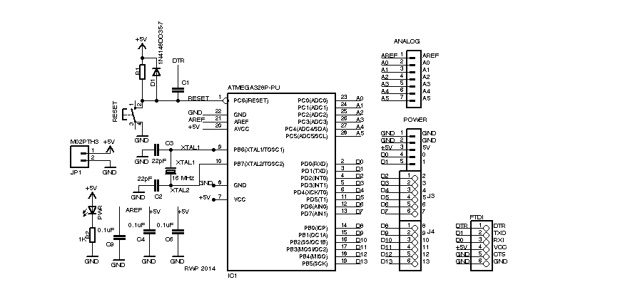
@CrossRoads Thanks for that schematic! I used the one from the arduino on a breadboard page here on arduino.cc but that schematic is somewhat different. I actually have one 10K pullup on the reset, one one the TX and one on the RX pin only. I did not know that a diode was required between RESET and the +5V ? And R1 is 110K ohm ? Also, I need a 0,1uF between VCC/aVCC and +5V ? I'm curious to know why that is required ?
EDIT: Oh I misread... One 10k pullup and not 110k pullup.