Arduino IDE version: 1.8.1
RFID LIBRARY - GitHub - miguelbalboa/rfid: Arduino RFID Library for MFRC522
MFRC522 Library version: 1.3.6
Arduino device: Uno
MFRC522 device: _RC522
Hey there,
I've been stuck on this situation for quite a while and any help is appreciated. I'm trying to connect my Arduino Uno to the RFID reader RC522. When I go to my serial monitor i am given the prompt below and am unable to view the RFID card UID using Dumpinfo:
Firmware Version: 0x0 = (unknown)
WARNING: Communication failure, is the MFRC522 properly connected?
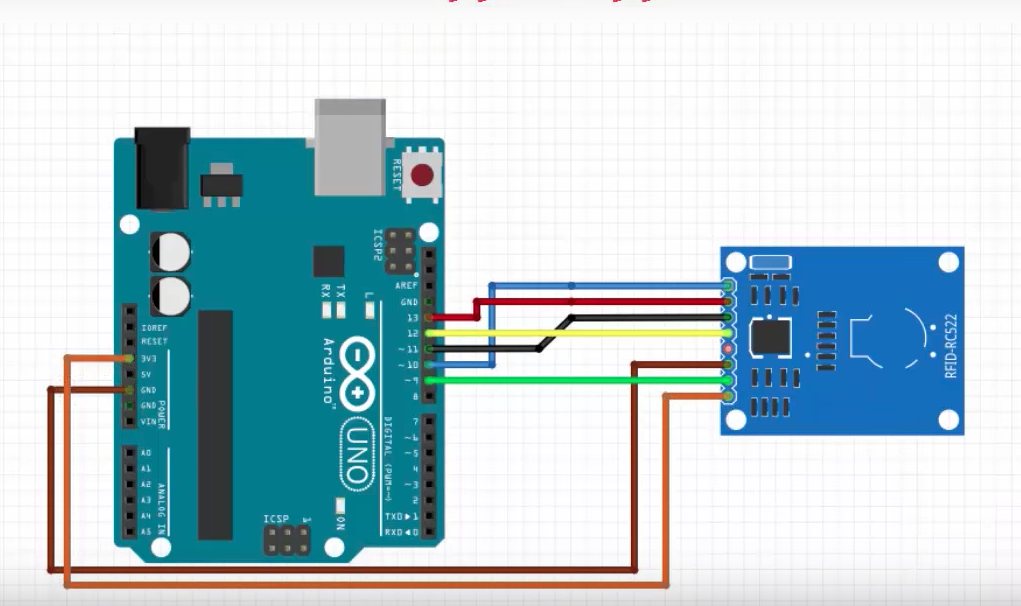
I have checked my pin layout and it looks like this:
MFRC522 UNO
RST 9
SDA(SS) 10
MOSI 11
MISO 12
SCK 13
/*
 * --------------------------------------------------------------------------------------------------------------------
 * Example sketch/program showing how to read data from a PICC to serial.
 * --------------------------------------------------------------------------------------------------------------------
 * This is a MFRC522 library example; for further details and other examples see: https://github.com/miguelbalboa/rfid
 *
 * Example sketch/program showing how to read data from a PICC (that is: a RFID Tag or Card) using a MFRC522 based RFID
 * Reader on the Arduino SPI interface.
 *
 * When the Arduino and the MFRC522 module are connected (see the pin layout below), load this sketch into Arduino IDE
 * then verify/compile and upload it. To see the output: use Tools, Serial Monitor of the IDE (hit Ctrl+Shft+M). When
 * you present a PICC (that is: a RFID Tag or Card) at reading distance of the MFRC522 Reader/PCD, the serial output
 * will show the ID/UID, type and any data blocks it can read. Note: you may see "Timeout in communication" messages
 * when removing the PICC from reading distance too early.
 *
 * If your reader supports it, this sketch/program will read all the PICCs presented (that is: multiple tag reading).
 * So if you stack two or more PICCs on top of each other and present them to the reader, it will first output all
 * details of the first and then the next PICC. Note that this may take some time as all data blocks are dumped, so
 * keep the PICCs at reading distance until complete.
 *
 * @license Released into the public domain.
 *
 * Typical pin layout used:
 * -----------------------------------------------------------------------------------------
 *             MFRC522      Arduino       Arduino   Arduino    Arduino          Arduino
 *             Reader/PCD   Uno/101       Mega      Nano v3    Leonardo/Micro   Pro Micro
 * Signal      Pin          Pin           Pin       Pin        Pin              Pin
 * -----------------------------------------------------------------------------------------
 * RST/Reset   RST          9             5         D9         RESET/ICSP-5     RST
 * SPI SS      SDA(SS)      10            53        D10        10               10
 * SPI MOSI    MOSI         11 / ICSP-4   51        D11        ICSP-4           16
 * SPI MISO    MISO         12 / ICSP-1   50        D12        ICSP-1           14
 * SPI SCK     SCK          13 / ICSP-3   52        D13        ICSP-3           15
 */

#include <SPI.h>
#include <MFRC522.h>

constexpr uint8_t RST_PIN = 9;          // Configurable, see typical pin layout above
constexpr uint8_t SS_PIN = 10;         // Configurable, see typical pin layout above

MFRC522 mfrc522(SS_PIN, RST_PIN);  // Create MFRC522 instance

void setup() {
	Serial.begin(9600);		// Initialize serial communications with the PC
	while (!Serial);		// Do nothing if no serial port is opened (added for Arduinos based on ATMEGA32U4)
	SPI.begin();			// Init SPI bus
	mfrc522.PCD_Init();		// Init MFRC522
	mfrc522.PCD_DumpVersionToSerial();	// Show details of PCD - MFRC522 Card Reader details
	Serial.println(F("Scan PICC to see UID, SAK, type, and data blocks..."));
}

void loop() {
	// Look for new cards
	if ( ! mfrc522.PICC_IsNewCardPresent()) {
		return;
	}

	// Select one of the cards
	if ( ! mfrc522.PICC_ReadCardSerial()) {
		return;
	}

	// Dump debug info about the card; PICC_HaltA() is automatically called
	mfrc522.PICC_DumpToSerial(&(mfrc522.uid));
}
 Tutorial")