I use an Arduino uno to operate a servo motor, which adjusts vane position on a Variable Geometry turbo in my truck.
It works great, except for one issue: when I attach my snow plow to my truck (electric over hydraulic plow), it draws a lot of current. So much current that it pulls my battery voltage down, and my Arduino stops working. When this happens I basically have no control over my turbo, and the only way to get it to work again, is to turn off my truck, and restart it.
My current set up takes 12v power, and runs it through a buck resistor to make 5v for my Arduino. I think I should add a capacitor and diode to keep the arduino alive and prevent the plow from pulling voltage from my Arduino.
Is this a logical thing to do?
If yes, how would any of you do it? Capacitor and diode on the 12v feed, or after the buck resistor on the 5v feed?
If no, what other options do I have?
Place a capacitor either across the output of the converter, or near the input to the Arduino. You may need to play with values to find the right one, but I'd say start with 1,000uF. Being on the 5V side, you only need a 10V capacitor (which means it's smaller than a 25V capacitor on the 12V side).
No need for a diode: the switching transistor(s) on the converter are doing that job.
Do I read this correctly? You are only using a resistor to drop 12V down to 5V for the Arduino? You should be using a power supply like a buck converter.
How are you regulating the 12V battery down to 5V for the Arduino?
Are you using a linear regulator, like a LM7812 or a buck DC to DC converter.
The buck converter would probably give better regulation in this instance.
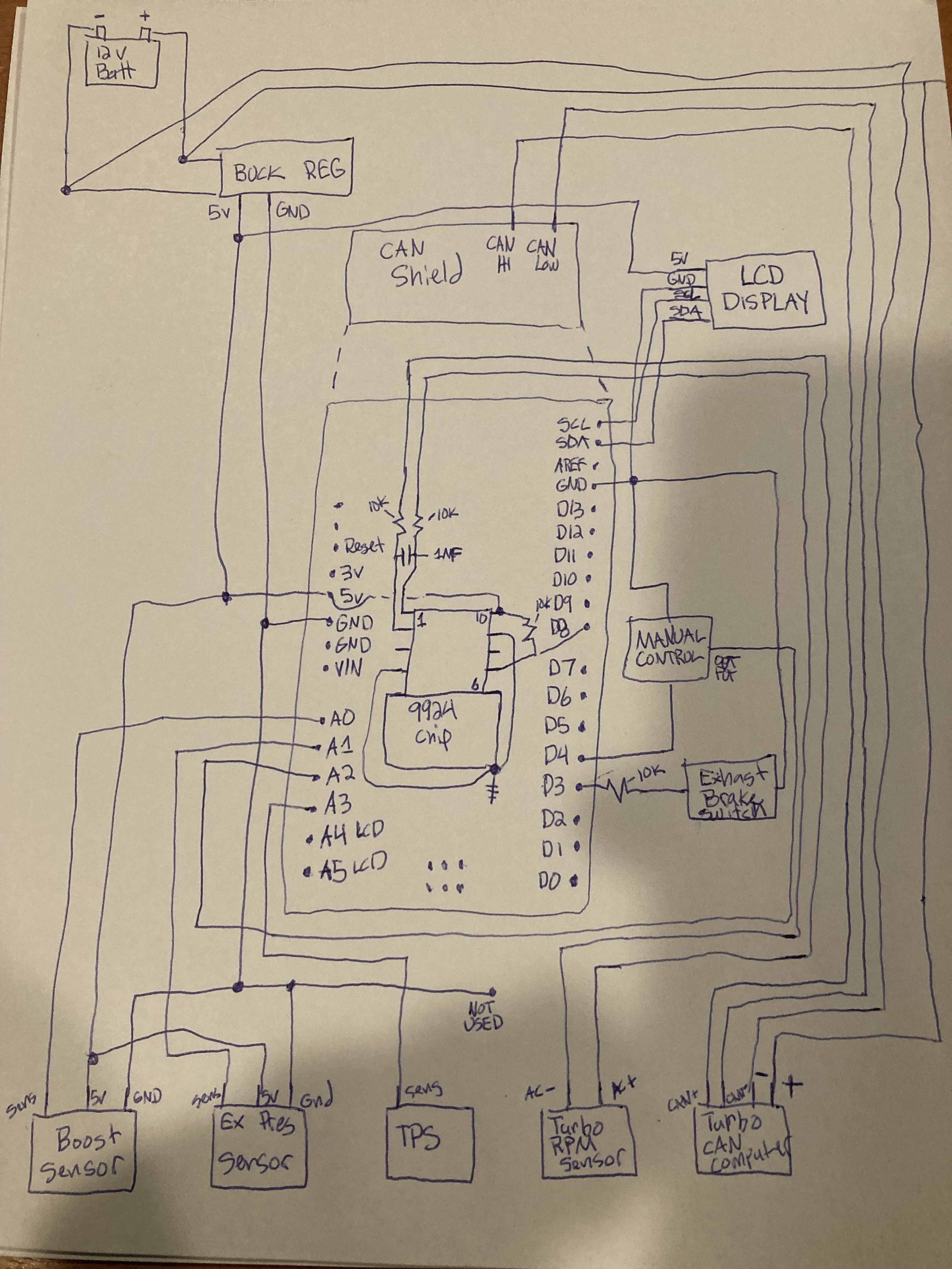
Can you please post a copy of your circuit, a picture of a hand drawn circuit in jpg, png?
Hand drawn and photographed is perfectly acceptable.
Please include ALL hardware, power supplies, component names and pin labels.
The first thing I’d recommend is replacing the buck converter with a SEPIC converter. What you’re experiencing isn’t unexpected, as the 12V system in vehicles can be very harsh. Looking at your schematic, it doesn’t seem robust enough for a vehicle environment. For starters, you're missing termination resistors and transient protection.
Your truck surely has two 12 volt batteries in parallel, just like mine. Are all 4 terminals clean and tight? Is the electrolyte level correct in both? What is the age of your batteries?
Yes. Truck has 2 batteries. 8 months old, clean terminals. This controller works flawlessly when the plow isn’t on. I have logged over 50,000 miles and many long road trips with it. I’m pretty impressed really.
It is obvious that the electrical demands of the plow affect the Arduino. As previously stated, when moving the plow a lot and working it hard, the arduino will go dead.
Are you specifically talking about the CAN BUS network wiring( As they lack 60ohm resistors and require those resistors to prevent electrical interference and allows communication over tha Can Hi and Can Low wires)?
Also- I have read a little about transient protection.
Would the best way to create transient protection be to put zener diodes between my sensor signal wires and ground? Or would it be between 5v supply to sensors and ground?
I think you’re confusing the bus impedance with the resistors. On CAN, the bus has a 60-ohm impedance, which comes from two 120-ohm termination resistors placed at each end of the bus. This is what results in the 60-ohm impedance.
I thought that those were terminating resistors. You had mentioned that my diagram lacks terminating resistors.
The only place I could see that required termination resistors were the CAN wires. I do not have them on the diagram because the canbus shield has them internally built in.
anyhow- back to my original concern: arduino stops working when aggressively operating snow plow.
I was thinking a diode and capacitor before the buck regulator would solve my problem, however; (as many have pointed out) the issue is most likely my buck regulator. You had suggested a SEPIC regulator. I looked up SEPIC regulators and am so confused as to which one to buy. I read through a bunch of tech sheets and cannot decide which one would be best to step 12v down to 5.
Does anyone have a recommendation on which one would work best for me?