Arduino UNO Code Compiled, Uploaded, but Not Working

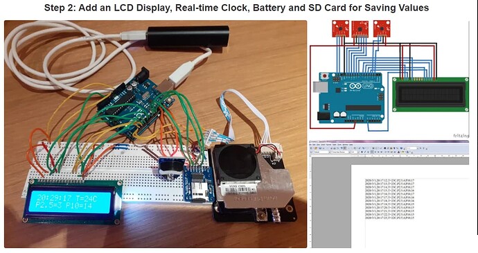
Hi, so for a school project I was required to make some device and essentially, I attempted to make a PM detector using the following tutorial: https://www.instructables.com/Simple-Air-Pollution-Monitor-Using-an-Arduino-Uno-/

I'm on this step and when uploading my code, the process goes smoothly but on the actual Arduino, I don't see any changes on the LCD Display, nor are any files created upon examining the SD card. It seems as if the code isn't functioning at all. Note the wiring is correct because I have rewired it multiple times in hopes of fixing the problem.

Using a Arduino UNO R3 hooked up via Usb to a standard computer USB port.

#include "RTClib.h"
#include <LiquidCrystal.h> 
#include <SD.h>
#include "SDS011.h"
 
LiquidCrystal lcd(14, 9, 5, 4, 7, 8);  
 
File myFile;
 
RTC_DS3231 rtc;
SDS011 my_sds;

int Contrast=80;
float p10, p25;
int error;
int y,z,T;

void setup () {
    Serial.begin(9600);
    my_sds.begin(2, 3);
analogWrite(6,Contrast);
     lcd.begin(16, 2);

  Serial.print("Initializing SD card...");
  // SD card pin output
   pinMode(10, OUTPUT);
 
  if (!SD.begin(10)) {
    Serial.println("SD initialization failed!");
    return;
  }
  Serial.println("SD initialization done.");


  delay(3000); // wait for console opening

  if (! rtc.begin()) {
    Serial.println("Couldn't find RTC");
  }

  if (rtc.lostPower()) {
    Serial.println("RTC lost power, lets set the time!");
    // following line sets the RTC to the date & time this sketch was compiled
    rtc.adjust(DateTime(F(__DATE__), F(__TIME__)));
    // This line can be used to set the RTC with an explicit date & time, for example to set
    // January 21, 2014 at 3am you would call:
    // rtc.adjust(DateTime(2014, 1, 21, 3, 0, 0));
  }
}

void loop () {
  error = my_sds.read(&p25, &p10);
  if (!error) {
    Serial.println("P2.5:" + String(p25));
    Serial.println("P10:" + String(p10));
  }
    DateTime now = rtc.now();
lcd.clear();
     lcd.setCursor(0, 0);  
     lcd.print(now.hour(), DEC);
    lcd.print(':');
    lcd.print(now.minute(), DEC);
        lcd.print(':');
    lcd.print(now.second(), DEC);
    
    lcd.print(" T=");
    T=rtc.getTemperature();
    lcd.print(String(T));
    lcd.print("C");

y = (int) p25;
z = (int) p10;
   
    lcd.setCursor(0, 1);

     lcd.print("P2.5=" + String(y));
     lcd.print(" P10=" + String(z));


      // open the file. note that only one file can be open at a time,
  // so you have to close this one before opening another.
  myFile = SD.open("PMlog.txt", FILE_WRITE);
 
  // if the file opened okay, write to it:
  if (myFile) {
    Serial.print("Writing to PMlog.txt...");
        myFile.print(now.year(), DEC);
    myFile.print('/');
    myFile.print(now.month(), DEC);
    myFile.print('/');
    myFile.print(now.day(), DEC);
    myFile.print(";");
   myFile.print(now.hour(), DEC);
    myFile.print(':');
    myFile.print(now.minute(), DEC);
        myFile.print(':');
    myFile.print(now.second(), DEC);
    myFile.print(";");
    myFile.print("T=");
    myFile.print(T);
    myFile.print("C");
    myFile.print(";");
     myFile.print("P2.5;" + String(y));
     myFile.println(";P10;" + String(z));  
  // close the file:
    myFile.close();
    Serial.println("done.");
  } 
  else {
    // if the file didn't open, print an error:
    Serial.println("error opening text file");
  }    
    delay(1000);
}
1 Like

We will see....
What's the output on serial monitor?

Here's a screenshot on serial monitor... It's stuck at initializing the SD Card I guess?

The SD Card that I have hooked up to the module is in FAT32, its a EMTC 16gb Micro SD card.

image

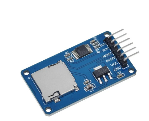
For more help, this is what the SD card shield I ordered looks like, and here's where I got it from: https://www.aliexpress.com/item/1005006005013220.html?spm=a2g0o.order_list.order_list_main.57.7f0a1802R2igyX

On the site, the option is called "TF Card Module". I have a feeling this issue is related to the SD card module- the tutorial only stated SD card module with little specification :frowning:

Maybe.
If you don't illustrate your wiring, I'm not able to help. I mean real wiring, that photo is from your tutorial.

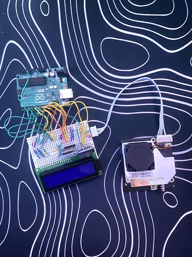
The real wiring is hard to understand because I've done it on a small breadboard. Nevertheless, the photo has been attached.''

1 Like

Difficult to see...
Where is GND?

also how is sdcard wired to arduino, pin to pin.

Did any steps you took involve getting just one of the external parts you are connecting to function correctly?

You have the LCD, the SD and an RTC, at least. Did you write or find a sketch for each of those that woukd let you test it, and your wiring, independently?


How many times do you have to rewire something to be certain the wiring is correct?

a7

1 Like

If I'm building this setup with aliexpress modules following some tutorial and it works out of the box, I'm running to buy a lottery ticket as well....

Try lcd.print("testing lcd");
right before the SD card stuff in void setup().
At least then you can narrow things down.
Did you adjust the contrast potentiometer on the LCD module? Sometimes that's all it takes to see the characters on it, even when it is lit up.

Should have double quotes around it. You have this a few times in your code.

The angle of the photo makes it hard to follow the pin alignment.
If the VO pin is connected to the 2nd blue wire ,that wire does not go anywhere.

image

From your code:

analogWrite(6,Contrast);

This pin should control the backlight (contrast).
You should see white blocks on the LCD , not to bright but just visible.

Edit: This pin should control the contrast.

Is the Backlight of the LCD on?

It wouldn't hurt, but is not necessary. The print() method is inherited and brings with it the ability to handle the same data types as it does for Serial objects:

data: the data to print (char, byte, int, long, or string)

Conspicuously absent are float and doulbe, a quick test just now shows at least the library I grabbed printed them, too. I would be surprised if a main-line LCD library did not handle all the same data types.

a7

Good eyes.
But not possible, author confirmed in first post that "wiring is correct" :wink:

1 Like

I stand corrected. I thought that was a one-way relationship (reading/declaring chars with single quotes but printing anything with double).

As I said before, it would be difficult to see because I'm using a small breadboard and it's all a mess.

The SD card wired to Arduino, pin to pin is a little different from the diagram (in the sense that DI/DO are replaced with MISO/MOSI), but should theoretically work (according to some sources online):

CS to Pin 10
SCK to Pin 13
MOSI to Pin 12
MISO to Pin 11
VCC to +Rail
GND to -Rail

I can indeed see white blocks on the LCD.

Yes the backlight to the LCD is on when I am actually testing it, in the photo it is not, but the LCD fully works when I connect the Arduino to power.

I followed your instructions, and as expected the LCD works. This was confirmed from the start, but I don't think I mentioned it in the post. Nevertheless, there is no issue with the LCD and the read/write code for LCD, I am suspecting the issue is with the SD card since serial monitor is stuck on "Initializing SD Card".