When calculating FFT, at the end there is a normalization (some kind of average) where the result is divided by the number of samples.
This means, that if the 60 Hz is present in all those samples, when divided by N (samples) it will still be there. For the signal of interest, that is not always present, when you divide by N, the energy value might be smaller. Not because the signal is weak, because is not present all the time.
So, the larger the amount of samples, you have better resolution. But, at the end, the math does some kind of weighted average, with a bias for those 60 Hz.
Thank you for the information and the link . Will digest it.
It makes sense that a constant 60 Hz noise and its harmonics during a short input-data reading span (my measured object's signal period is between 40us and 1ms) may end up dominating the FFT values. Especially if the input-data reading process period took much longer than the period of the measured object's signal period.
Not sure, if continuous input data background sampling is better with a trigger threshold (like if signal goes above 1V from the below 120mV idle state) ....or if an interrupt based (1V threshold trigger) one-shot sampling with a set period of sampling length is better?
This was the 60 Hz noise as I measured it with the alligator clip wire "antennae".
What is the amplitude of your signal before amplifying? First thing is to have a clean input.
The way to avoid interferences is to amplify as soon possible and as close as possible to the signal, to avoid amplifying the noise along with the small input signal.
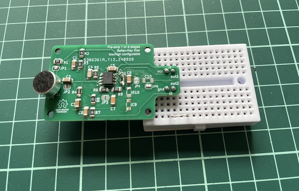
I do some projects with bats ultrasounds. For testing, I have created a small PCB just to amplify, where I can feed the input signal very close to the opamps. In this case a mic, but could be anything.
In the final design the input is even closer to the opamps.
This PCB can be setup with any SOIC-8 opamp as: one ampl stage + buffer, 2 ampl stages, or 1 ampl stage + 2nd order filter.
And you should power it for example with a small AAA battery in a holder with 2 jumpers.
This is still just for testing. At the output you have a strong signal without noise (almost), that you can send to the MCU or ADC with short wires. But the noise will be not critical there, with a 2V or 3V signal. At least for testing.
Ok, 300mV is not bad. The signal that I get is about 5mV - 30mV before amplification, and it works fine.
Your inteference is about 120mV peak to peak, right? You have to avoid that into your signal. Remove any jumper, breadboard or wire that is not shielded between your signal and the opamps. And put it as close as possible. And if possible use a battery or a small powerbank to power it.
I came across an (older) FFT library and a blog that is primarily made for audio processing and Teensy.
It uses Arm's MBED and the CMSIS DSP FFT library. The "simple" FFT sample has an Inverse FFT flag, And also there are couple of Arduino ino files that do FFT window design, " samples in the time domain, FFT to convert to frequency domain, manipulates the frequency bins as desired (LP filter? BP filter? Formant shift?, takes IFFT to convert back to time domain, sends samples back to the audio interface, noise canceling", Tympan, overlap, etc (many of which I am not familiar with). The more complex tasks were written for use with a Teensy Audio shield, but seems like that can by-passed in the code for ADC input,
This sample FFT library file complies and runs for Teensy 3.2, and XIA 52840 BLE, but just sits idle after printing via Serial the real and imaginary FFT values.
Then I found this other Arm ino that complies and loads for XIAO 52840 BLE (also with Inverse FFT option), but haven't figured out yet how to do a conversion from float array so I can print out the values with Serial.print.
#include <arm_math.h>


#define TEST_LENGTH_SAMPLES 2048

static q31_t testOutput[TEST_LENGTH_SAMPLES/2]; // all types changed from f32 to q31 just to see if it mattered

uint32_t M = 0;

/* ------------------------------------------------------------------

Global variables for FFT Bin Example
------------------------------------------------------------------- */
uint32_t fftSize = 1024;
uint32_t ifftFlag = 0;
uint32_t doBitReverse = 1;
/* Reference index at which max energy of bin ocuurs */
uint32_t refIndex = 213, testIndex = 0;

/* ----------------------------------------------------------------------
Test Input signal contains 10KHz signal + Uniformly distributed white noise
** ------------------------------------------------------------------- */

q31_t testInput_f32_10khz[TEST_LENGTH_SAMPLES] =
{
-0.865129623056441, 0.000000000000000, -2.655020678073846, 0.000000000000000, 0.600664612949661, 0.000000000000000, 0.080378093886515, 0.000000000000000,
-2.899160484012034, 0.000000000000000, 2.563004262857762, 0.000000000000000, 3.078328403304206, 0.000000000000000, 0.105906778385130, 0.000000000000000,
-1.620990298572947, 0.000000000000000, -1.085103073196045, 0.000000000000000, 0.738606361195386, 0.000000000000000,
-2.097831202853255, 0.000000000000000, 2.711952282071310, 0.000000000000000, 1.498539238246888, 0.000000000000000, 1.317457282535915, 0.000000000000000,
-0.302765938349717, 0.000000000000000, -0.044623707947201, 0.000000000000000, 2.337405215062395, 0.000000000000000, -3.980689173859100, 0.000000000000000,

};

void setup() {
 Serial.begin(115200);
}

void loop() {


      /*\example arm_fft_bin_example_f32.c
 */


arm_status status;
arm_cfft_radix4_instance_q31 S;
q31_t maxValue;

status = ARM_MATH_SUCCESS;

/* Initialize the CFFT/CIFFT module */
status = arm_cfft_radix4_init_q31(&S, fftSize, ifftFlag, doBitReverse);

/* Process the data through the CFFT/CIFFT module */
arm_cfft_radix4_q31(&S, testInput_f32_10khz);


/* Process the data through the Complex Magnitude Module for
calculating the magnitude at each bin */
arm_cmplx_mag_q31(testInput_f32_10khz, testOutput, fftSize);

/* Calculates maxValue and returns corresponding BIN value */
arm_max_q31(testOutput, fftSize, &maxValue, &testIndex);


if(testIndex !=  refIndex)
{
	status = ARM_MATH_TEST_FAILURE;
}

/* ----------------------------------------------------------------------
** Loop here if the signals fail the PASS check.
** This denotes a test failure
** ------------------------------------------------------------------- */

if( status != ARM_MATH_SUCCESS)
{
	//while(1);
}

}
If you just need the main dominant frequency, or the first few, you could use the autocorrelation frequency method. It is simpler and faster for the MCU.
I don't know if there are Arduino libraries, but is not difficult to program just by multiplying your samples arrays against itself shifted.
I was wondering that also.
Could be that the gain is a bit less, because of the resistor divider in the output, and the capacitors in the feedback. If C14 is really 100pF then it reduces the gain a lot for 1KHZ - 5KHz.
But yes, could be that most of the signal is noise.
(I have not read all the long explanations...)
Measured it just now, and the idle voltage as it reaches C9 on the diagram reads 16mV VPP (-2mV to 8mV, but likely -8mV/+8mV). That is without any external trigger such as movement, etc.
This 16mV VPP changes with movement in front of the sensor, and based on the 5VDC peak voltage I read after the two op amps, that range is about -25mV/+25mV. But at times the DC signal which is centered at +2.5V goes beyond the 0V/+5V range with large/fast objects, so possible that it's even higher than -25mV/25mV, but unlikely to be in the -300/+300mV range.
The sensor data I posted above was from one of the radar sensors I have that I considered using in my own future circuit. The current sensor is built in to the radar device and came with it and I should have given some thought examining it better.
EDIT: I am quite sure that this is the HB100 doppler module, or a Chinese version of it, with the following specs:
I was not able to test the capacitors properly, only in circuit, because they are on the PCB and did not dare to remove them as they are twice smaller than I ever soldered before. I "calculated" their values based on the other similar design I posted above, and based on their function in the circuit. The radar device was designed to measure about 1,25 Khz to 25khz (period between 1ms to 40us)
Yes, I only need the main dominant frequency, one single number. I am not familair with the autocorrelation frequency method, so will look into it to understand the concept.
EDIT: here are two interesting links on the autocorrelation subject with sample codes for me to digest. (So it's not FFT at all ! ):
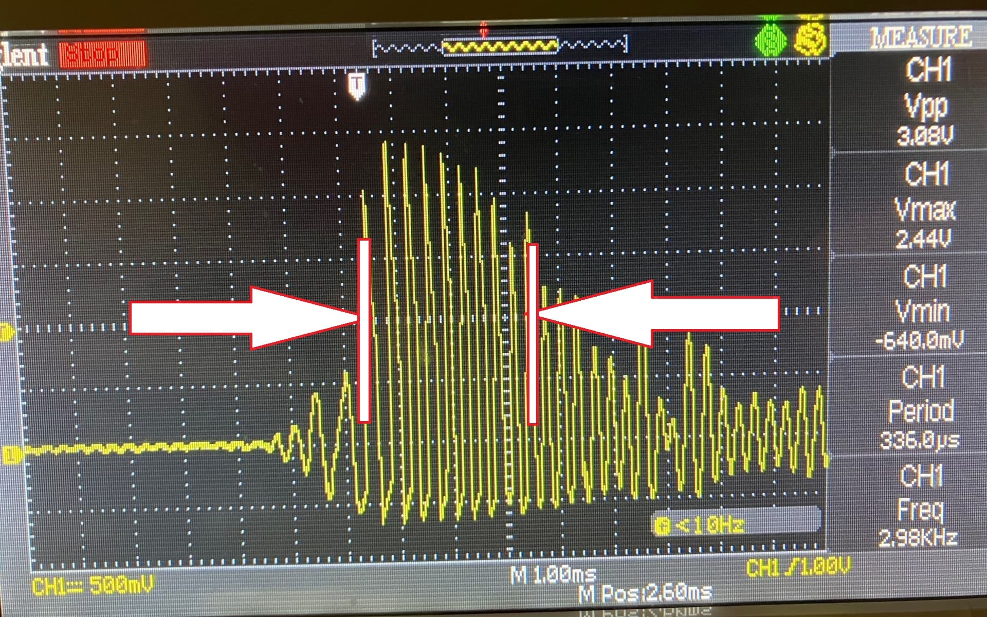
This is what a typical signal will look like. For my purposes, it will always be between 1 Khz and 25 Khz and the frequency never exceeds the 1ms period length. But the entire signal is about 6-8ms in length (so the sampling envelope should be minimum that long, or continuously sampled. And from that array the FFT must grab that dominant peak area at the beginning. And sampling needs to be accurate down to 40us with about 1% accuracy.
What's ironic is that my oscope gets it correct every time. I wish I could just transplant the algo from it into a smaller footprint
I am sure it's not the op amp. The MCU board I am using has this noise without anything connected to it. I tried three different boards made by different companies. Even if I unplug the board from power and leave the ADC pin and GND connected to the oscope probe, I get the 60 Hz noise IF I have longer leads between them.
When I can have the oscope probe unconnected, and I clip a standard 20" alligator clip wire to it, I can instantly see a 60 Hz or harmonics wave of about -30/+30mV (60mVPP). So if I connect that alligator clip to my board's ADC pin, instant noise gets added. The connecting wire(s) are like antennas.
If I clip the oscope probe directly to the half inch pins of the board while the board is powered, the noise goes down to -8/+8mV (16mVPP) and loses its 60 Hz sine wave shape, and the oscope cannot pick up a clear frequency anymore. I placed a large aluminum foil on the GND between the board and the oscope and it went down further to about -3/+3mV (6mVPP).
Yes, but the noise in that side is not the bigger problem. A few mV of noise when your signal is already 2V or 3V is not that bad.
But as Jim said probably your input signal is much smaller. So the problem is the noise before the preamp.
Imagine that your signal is about 5mV, and the noise at the input is also about 5mV (being optimistic). Then together with your signal, the noise will be also multiplied by 1000.
And the result is garbage with more noise than information.
I don't know what is the real situation. But pay attention first to the signal at the input; short wires, etc.
As I have been saying all along, untill you have an opamp circuit that provides the required gain, offset, and filtering you are just wasting your time with the code.
Due to the long thread, I think some important details may have been lost. I do have a perfectly functioning radar device that has a perfectly functioning sensor + op amp + MCU with firmware. I understand now better (with your help) what is required to get good sensor input data to the MCU residing on the PCB of a yet to be built radar device of my own.
The problem I have now is that I was not able to get good data into my separate MCU test board. That test board's only purpose is to help me develop a signal processing code that works. A code that accomplishes the same task as the firmware that is on the radar device MCU itself.
The problem I had is that I was using dupont wires alligator clip wires between the radar device PCB and my test MCU board which skewed the FFT readings. It did not help either that the ArduinoFFT code seems to be half-backed apparently and full of errors.
I see three paths ahead:
build my op amp board and populate it with my own sensor, op amp and MCU. Then test for a working code. This basically would recreate the perfectly working device I already have, but would ensure that the MCU signal input is clean.
Use Mathlab or similar and bypass my MCU test board and process the existing PCB board's signal from capacitor C36. This would require for me to learn Mathlab, etc which is useful but quite a detour for a non-professional hobbyist just for getting one FFT code working. And then there is still the question of interfacing the PCB board to a PC port.
Use the existing perfectly functioning radar device and fix the interference problem between capacitor C36 and my test board.
I will go with #3, for now first. I have a shielded cable, and will use short leads and a larger ground. The signal I am tapping into at capacitor C36 is after the dual op amp output and is already AC at 0-+2.5V range. The mistake I made was that the connecting wires and oscope probe connections I used for testing acted like an antenna that introduced a 60 hz+ alias in the otherwise good signal going to the ADC pin of my test board. I am also switching over powering the device via battery, albeit the major issues I gather were connecting wires.