No. You must set the fuses before you can use the reset pin as an input pin. After that, the pin is no longer the reset pin and you cannot use an ISP programmer (including ArduinoISP) to upload code to the chip.
If you buy a digiSpark board, the fuses have already been set for you and you can upload code through USB.
If you can say more about how the project will operate, relating to the LEDs, maybe we can suggest a way to save 1 or 2 pins so that you do not need to use reset pin as an input. For example by using ws2812 or apa106 LEDs.
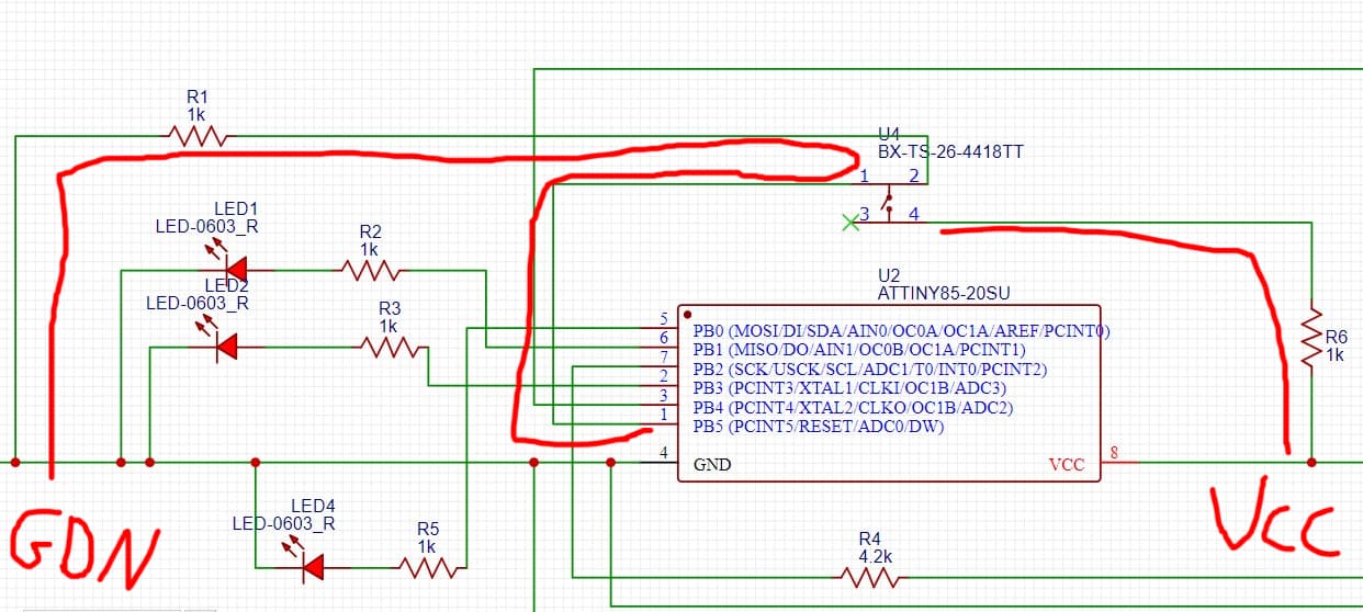
Your schematic shows 1K between the PB5 and ground, and another 1K between the button and Vcc. This is not a correct way to connect a button and will not work.
When the button is not pressed, the pin will read LOW reliably. But when the button is pressed, the pin will see a voltage of Vcc/2 and will not reliably read HIGH or LOW.
According to your first answer since reset pin is already fused in digispark board so can i upload the code to digispark attiny85 then simply desolding the attiny85 and mount on my pcb?
In fact you can use the reset pin as input pin, while it is still active as Reset. But you have to keep the voltage level above 2.5Volt (if you feed the Attiny with 5 volt on its VCC pin). Last week I was just playing with the peripherals of the Attiny85 and below sketch demonstrates the use of the reset pin as input . I used a potmeter to be able to feed the reset pin with a variable voltage. That way you can also measure with a multimeter at what voltage the Attiny will go into a reset status.
/*************************************************************************
   Attiny85 two tone beeper on SCL pin PB2 (mis)using only ADC and USI
   Uses none of the 8-bit timers or watchdog timer)
   Connect a passive beeper to SCL pin PB2
   Connect a (10K) potmeter between GND<>RESET<>VCC
 *************************************************************************/

void setup() {
  DDRB |= _BV(PB2);//set SCL as output
  USICR |= _BV(USIOIE);// USI 4 bit Counter Overflow Interrupt Enable
  ADMUX = _BV(ADLAR); // left adjust ADC result for only using ADCH connect to RESET
  ADCSRA = _BV(ADEN) | _BV(ADSC) | _BV(ADATE) | _BV(ADPS2);  // Enable ADC in free running mode.
}

void loop() {
  if (ADCH > 250) ADCSRA &= ~_BV(ADIE); // turn off sound by disabling the ADC interrupt.
  if (ADCH < 240 && ADCH > 200) ADCSRA |= _BV(ADIE) | _BV(ADPS0); // turn on Low tone
  if (ADCH < 190) ADCSRA &= ~_BV(ADPS0); // change to High tone
}

ISR(USI_OVF_vect) { //interrupt service routine when USI timer overflows
  USICR |= _BV(USITC);// toggle the SCL port by writing one to this bit
  USISR |= _BV(USIOIF);// clear the USI Counter Overflow Interrupt Flag
}

ISR(ADC_vect) { //interrupt service routine when ADC completes conversion
  USICR |= _BV(USICLK);// strobe the USI clock
}
No that won't work as now your reset can never go below 5V. You tied it to VCC directly
I meant to say that that Attiny85 needs to be fed with 5V in its VCC pin.
I changed my previous post to reflect that more clearly.
You designed a voltage divider in your original schematic that will pull the reset pin to 2.5Volt when the button is pressed. Can you clarify your thoughts behind that?
I would suggest to make R1 3K and keep R6 1K. Then the button will pull the reset pin voltage from 5V to 3.75 Volt, which is more than enough to be sensed by the ADC.
i saw some diagrams add resistor between reset and the vcc so i added it, but removed it after paulRB post #5
sorry did not understand why use voltage divider to keep the voltage above 2.5v while i can get 5v from the vcc (which is bigger than 2.5v)
can you explain why do not directly give 5v to the reset pin if you could?
so by adding so two resistors to 3k and 1k, the reset pin should work as input pin?
When the reset pin drops below (approx) 2.5Volt the Attiny will reset.
During normal operation you need to be sure that the voltage of the reset pin stays at the HIGH level.
That is the reason why people put a so called "external pullup resistor" between the reset pin and VCC. That resistor will "pull" the voltage of the pin to VCC.
Why a resistor and not just tie reset to VCC?
Well, then you cannot reset it anymore. With the reset pin tied to VCC directly you can never pull it to GND anymore to make it go below 2.5 Volt. You would create a short circuit between VCC and GND, which is usually not a good idea.
With a 1K resistor in place you can still connect the reset pin briefly to ground to reset. The resistor will prevent against a short circuit and only a small amount of current (5V / 1000 Ohm = 5 mA) will flow through the resistor during reset.
With the two resistors in place you can use the reset pin as analog input pin (analogRead) not as digital input pin.
so i think i do not need any resistor between pin reset and the battery i measure (lipo 3.7v) since the battery will provide the voltage above 2.5v and will not reach to 2.5v so will not reset
lipo battery will be connected to tp4056 (charging module) --> mt3608 (boost converter 3.7 to 9v) (9v to feed the motor) --> regulator 5v --> attiny85 vcc
and other vcc and gnd from lipo to the reset pin to read the voltage
I think I see a transistor without a base resistor. If you make that a logic level mosfet it can work. Otherwise better add a base resistor.
Connecting the lipo to the reset pin should work, as it will keep the voltage between acceptable range, without resetting the Attiny.
You may want to think about a further simplification where you feed the Attiny directly from the lipo and still measure the voltage of the lipo. There seems a way to do that via the bandgap reference and a formula. Then you don't need the 5V regulator and you don't need the reset pin.