Automated Allotment Watering System - Project Diary

Hi all,

I thought I would share my current home project, partly to keep as a project record as it will expand beyond just watering, and also to share with others who maybe wishing to do something similar.

We recently became the tenants/owners of an allotment, and one of the issues we faced over the last few weeks is getting there every day to keep on top of the watering of the plants/crops, especially in the heat we've just had (I'm in the UK). So I thought I'd put together a solar powered watering system.

I'm keeping it fairly basic for now and just using a timer system so it waters the plants twice a day at set times. Future changes will try to include moisture sensors in the pots which will trigger the system to switch on. There are pros and cons to both the current and proposed systems, so it'll be a case of trial and error until I find the sweet spot.

I think the worst of the hot weather is over now, so it's not to critical but I'm going to fit all the kit tomorrow and get it going for the remainder of the summer.

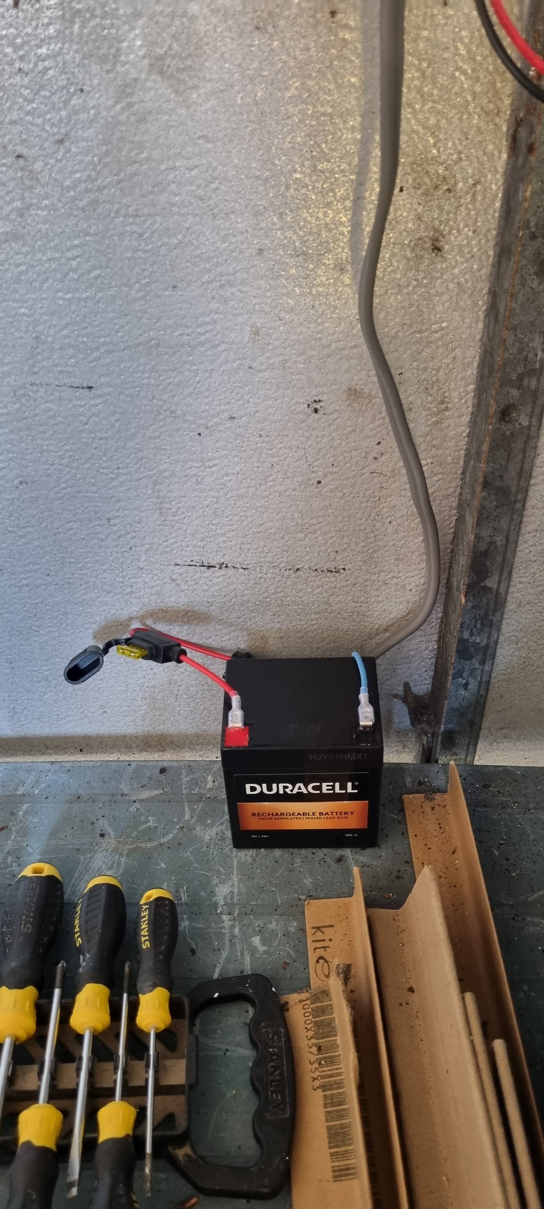
I'm using a 12v 10w solar panel which will charge the 12v 5ah battery via the charge controller. This will then power the nano via the vin. The nano uses a RTC to keep an eye on the time and when it 'sees' it's time to water the plants it controls a 5v relay to switch on a 12v 2A water pump that sits in the water butt. The pump runs for 10 mins (although this might change once it's installed) and waters the polytunnel plants using a micro irrigation system.

The pump puts out 12l/min @ 0.6bar using a standard hose diameter. The hose diameter is then reduced to 4mm, which is the size of the tubing for the micro irrigation system. Whether or not the 0.6bar is enough to pump the water through the whole of the system I am yet to find out. If it isn't I have another high pressure diaphragm pump that I can fit into the system that will get the job done, but uses more power too. As I'm only using a 5ah battery and a 10w panel, I want to keep power consumption low.

There is a float switch on the IN line of the relay to cut off the relay should the water level of the water butt get too low and to stop the motor burning out.

I've also included a momentary push button to start the pump for a couple of minutes with the ability to stop it again if it hasn't reached the full 2 mins. This is for on demand watering, for example I could install a manifold on the hose and switch off the micro irrigation and switch on a normal hose to use for blasting the kids with or something else.

Future plans are to swap to esp32, install temp and humidity sensors, install wifi (to monitor and control remotely ) and increase watering capability.

I will be going to the plot tomorrow to install what I have up to now and get things going.

The code could do with some refining, however, it works and for now I'm happy with that. I am also happy to take any constructive advice regarding the code.


[Edit - Parts list]

.......and all the other bits and pieces to connect it all together.


Current build photos

Code (I'm using VS Code to write it)

#include <Arduino.h>
#include "RTClib.h"
#include <SPI.h>

RTC_DS3231 rtc;

//--------------------------------------------------------------------------------------------------

//Variables

bool DEBUG = true; //Turn Serial Output on/off
bool morningWaterComplete = false; //has the morning watering taken place?
bool afternoonWaterComplete = false; //has the afternoon watering taken place?
bool overrideSwitchPressed = false; //has the pump override switch been pressed?

uint8_t moringWaterTime = 07; //Set time for morning watering in 24hr
uint8_t afternoonWaterTime = 18; //Set time for afternoon watering in 24hr

unsigned long minuteCheck = 60000; //Used to check if 1 min has passed, in milliseconds
unsigned long timeElapsed;
unsigned int waterPumpDuration = 10; //Run water pump for 10 min, in minutes
unsigned int overrideDuration = 2; //Run water pump for 2 min, in minutes

int waterPump = 12; //Pin to control water pump
int switchPin = 9; //Pin switch is connected to

int currentButtonState = 0;
int lastButtonState = 0;
int buttonState = 0;
unsigned long lastDebounceTime = 0;
unsigned long debounceDelay = 50;


//--------------------------------------------------------------------------------------------------

//****Forward Declerations******//
void begin_RTC();
void checkTime();
void waterPlants();
void runWaterPump();
void timerOverrideSwicth();
void runWaterPumpOverride();

//--------------------------------------------------------------------------------------------------

void setup() {
  // put your setup code here, to run once:

  Serial.begin(115200);

  begin_RTC();

  pinMode(waterPump, OUTPUT); //set waterPump as output pin
  timeElapsed = millis();

}

//--------------------------------------------------------------------------------------------------

void loop() {
  // put your main code here, to run repeatedly:

  checkTime();
  timerOverrideSwicth();

}

//--------------------------------------------------------------------------------------------------

void begin_RTC(){ //Start RTC.

  if(!rtc.begin()){

    if(DEBUG) {Serial.println(F("Cound not find RTC!"));}
  }
  else {

    DateTime now = rtc.now();

    if(DEBUG) {Serial.println(F("RTC Initiated!"));}

  }

    DateTime now = rtc.now();

        
    //rtc.adjust(DateTime(F(__DATE__), F(__TIME__))); //Set RTC time for 1st complile or if RTC looses time.

    if(DEBUG) {Serial.println("Time set:");

      Serial.print(now.hour(), DEC);
      Serial.print(':');
      Serial.print(now.minute(), DEC);
      Serial.print(':');
      Serial.println(now.second(), DEC);
    
    }

}


void checkTime(){ //check to see if 1min has elapsed. If so, check if it's time to water the allotment.

  if ((millis() - timeElapsed) >= minuteCheck){

    timeElapsed = millis();
    waterPlants();

  }

}

void waterPlants(){ //Check if it's time to water the allotment.

  DateTime now = rtc.now();

  if ((now.hour() == moringWaterTime) && (morningWaterComplete == false)){ //Turn pump on for morning watering session

    if (DEBUG) {Serial.println(F("Beginning Morning Watering"));}

    runWaterPump();

    if (DEBUG) {Serial.println(F("Morning Watering Complete"));}
    
    morningWaterComplete = true;
    afternoonWaterComplete = false;

  }


  if ((now.hour() == afternoonWaterTime) && (afternoonWaterComplete == false)){ //Turn pump on for afternoon watering session

    if (DEBUG) {Serial.println(F("Beginning Afternoon Watering"));}

    runWaterPump();

    if (DEBUG) {Serial.println(F("Afternoon Watering Complete"));}

    morningWaterComplete = false;
    afternoonWaterComplete = true;

  }


}

void timerOverrideSwicth(){

    currentButtonState = digitalRead(switchPin);

  if (currentButtonState != lastButtonState) {
    lastDebounceTime = millis();
  }

  if ((millis() - lastDebounceTime) > debounceDelay) {
    if (currentButtonState != buttonState) {
      buttonState = currentButtonState;

      if ((buttonState == HIGH) && (overrideSwitchPressed == false)){

        
        overrideSwitchPressed = true;
        if (DEBUG) {Serial.println("Button Pressed");}
        runWaterPumpOverride();

      }

      else if ((buttonState == HIGH) && (overrideSwitchPressed == true)){

        overrideSwitchPressed = false;
        digitalWrite(waterPump, LOW);

        if (DEBUG) {Serial.println("Button Pressed");}
        
      }

    }
  }
  
  lastButtonState = currentButtonState;

}

void runWaterPump(){ //Run water pump for 10min

    unsigned long waterTimer = millis();    
    if (DEBUG) {Serial.println("Water Pump - ON");}

      while(millis() - waterTimer <= (waterPumpDuration * 60000)){
        
        digitalWrite(waterPump, HIGH);

      }

  digitalWrite(waterPump, LOW); //turn off water pump
  if (DEBUG) {Serial.println("Water Pump - OFF");}

}

void runWaterPumpOverride(){ //Run water pump for 10min

    unsigned long waterTimer = millis();    
    if (DEBUG) {Serial.println("Water Pump Override - ON");}

      while(millis() - waterTimer <= (overrideDuration * 60000)){
        
        digitalWrite(waterPump, HIGH);
        timerOverrideSwicth();

        if (overrideSwitchPressed == false)
         break;         
         
      }

  digitalWrite(waterPump, LOW); //turn off water pump
  if (DEBUG) {Serial.println("Water Pump Override - OFF");}

}

Thanks for reading :slight_smile:

2 Likes

A word of caution...

07 is not base 10. In this case it won't matter. Sometimes it does.

Look for the marked line...

This will avoid a drifting clock...

Very nice asynchronous code.

1 Like

Thanks for the comments. I've just closed down the laptop, I'll have a look first thing tomorrow :slightly_smiling_face:

Could you explain a little more about your base 10 comment please?

Numbers starting with a 0 tell to the compiler they are written using an Octal base.

So 012 is an Octal representation for example and is worth 10 in decimal

07 and 7 are the same as 7 is less than 8 but 09 does not exist

Hence the need to be careful- you probably did not intend to use base 8 / octal :slight_smile:

2 Likes

Thanks for the explanation! Another lesson learnt! I'll edit the code tomorrow :+1:

1 Like

I fitted all the kit today and got it all running. Pump worked on pressing the button and battery charged. Result....kind of.

Something happened as I was packing away. I slid the battery across the table just so it wasn't in the middle of the table. I heard the ground connection arc/buzz a little. So I pushed the spade connector on just to make sure it had good contact and as soon as I done this....the nano let the smoke out. Why do you think this happened?

I have no idea. It was fine all day and just the wiggle of the spade connection caused the nano to pop. I have to say the spade connectors I bought from Amazon are pretty much made of cheese. They have no strenth to them despite being the right size for the battery.

I'm powering the nano with 12v via the VIN which is good for 20v. I've never had an issue with 12v in the past. I have quite a large spare buck converter in my box (its a XL4016 which is good for 40v in), could this be used almost as surge protection?

Anyway, I'm rebuilding it but with female headers this time so I can swap the board easily if it happens again.

I am aware I'm using cat6 cable for powering the pump and should really be using something better...but I had it to hand so it got used used.

Some photos from today...


1 Like

Bummer.

Even with a schematic it may be difficult to tell.

1 Like

Yeah, im putting it down to some sort of electronic gremlin that I don't understand to do with a fully chaged battery and lack of or poor surge protection in the charge controller. Honestly, I don't actually know and I'm just making it up.

I'm also making up the solution which is to install the buck converter between the charge controller and the nano and hope it deals with any voltage spikes. Who knows. It makes sense in my head, but at this point I'm just guessing.

Rebuilt the board from scratch but I can now just pull the board off if it fries again.

1 Like

It may be that the Nano cannot power what I assume is a 5V relay from a fully charged battery (13~14V).

You read that the Nano's Vin pin is "good" for up to 20V. Well, maybe, as long as the only thing being powered is the Nano itself. But if you power other devices from the Nano's 5V pin, it's very likely to burn out its weak and vulnerable on-board regulator. An RTC needs very little and probably isn't a problem, but a 5V relay definitely is.

I assume (in the absence of a schematic or even a parts list) that you are using a 5V relay? When you have a 12V supply, a 12V relay is more appropriate. Then the relay can take power directly from the battery and not overload the Nano's regulator. Better still would be a logic-level MOSFET.

Another thing to check is that you have a flyback diode across the pump? Without that, when the pump is switched off, a large negative voltage can be generated by the pump's motor for a moment, damaging other components.

Yes, use a buck converter. Set it to output 5V and connect it to the Nano's 5V pin, not Vin. That means the on-board regulator is bypassed completely.

1 Like

Hi Paul,

Thanks for your reply.

I am using a 5v relay, powered from the nano. I understand what you're saying, and might have to go back to the plot to rearrange things after my visit today.

Hopefully it'll be ok for the time being as it's only powering the RTC.....and the relay for 10min...

Good point. I'll edit my first post later on and give a complete parts list (and maybe a schematic if I get time)

Can the 5v nano drive the coil on a 12v relay if the relay is powered by an alternative 12v source? If so, then that'll work. If not, then I'm not sure how the nano would switch the relay.

What I can do is rearrange things so the relay is powered from the buck converter and the nano pin switches it on and off.

I'll consider this when I next make a mod, which will likely be in the coming weeks/months when I add a 10w LED floodlight for the incoming darkness.....

Again, good point and thank you. I have one on the solar panel, didn't think to put one on the motor. Hopefully the way I have it arranged after todays visit will help with any issues before I fit one.

I fitted the buck converter today. However, I set it at 6v and sent it to the VIN pin as I wasn't sure of the tolerances for the 5v pin....does it have to be bang on 5v or is there some wiggle room? The buck converter was difficult to get exactly 5v using the little screw earlier so I set it at 6 and put it in the VIN.


I fitted some new and smaller/tighter spade connectors for the battery today which seemed to work a lot better once I'd eventually got them on.

Todays photo update showing the buck converter.

Also made a little shelf from some scrap to keep the battery out of the way of people using the table.

Just need to tidy up the cables and then get the irrigation hose routed in the polytunnel.

Yes. To be precise, the Nano can drive a 12V relay module. A low voltage/low current signal from the arduino triggers a transistor and/or opto-isolator on module, which in turn energises the relay coil using power direct from the 12V source.

The diode on the pump/motor serves a very different purpose than the diode on the solar panel. With the panel, the diode is connected in series, preventing the battery from discharging through the panel during the night. With the pump, the diode is connected in parallel to allow any negative voltage, created when the pump is switched off, to discharge though the diode, rather than damaging other components in the circuit.

Anything from 4.5~5.5V should be fine.

1 Like

Nice one @PaulRB ,I appreciate the help :+1:

This does depend on the module and if you have the jumper on or off. Make sure your arduino provides logic not power. Particularly make sure it is not directly connected to the coil or it will likely be killed by massive voltage spikes unless there is appropriate fly back protection. A proper module should allow complete opto-isolation of the arduino

This is the first time I have used relays and I get the feeling there is some additional reading to be done here.

So my understanding so far is, I can switch the relay using a nano pin that is switched to high on an event to control the water pump etc, but the relay itself must be powered (ideally) from an alternative source - such as the 12v load side of the charge controller?

A good way of dealing with projects is to break everything down into their basic parts and understand their interactions. Arduino is a microcontroller and does not power things but provides brains. Brains are sensitive things. It creates logic signals only at its pins (low voltage, very low current) and you can set them to occur depending on any condition you like.
Relays are chunky things that switch power for heavy loads. The load side is generally independent of the coil side but interference can occur. The coil is a large load in itself (compared to an arduinos capabilities) and is inductive ie it creates a large electromagnetic field when powered and when power is removed that field collapses and releases its energy. This can cause voltage spikes that are way way above what an arduino wants to see.
Relay modules are a module that contains a relay and “other stuff”! The other stuff depends on who made the module and can be anything but often includes a way to isolate the signal circuit from the chunky coil side to avoid damage to the uC(microcontroller). This might be opto-isolation (where light is used to electrically isolate one side from the other while still transmitting the signal). There is normally a “jumper” on these boards that allow isolation to be on or off. You need to understand your module.
Fly back diodes are used to allow the collapsing field to dissipate and may be needed on the coil side or the switch side if an inductive load is powered.

2 Likes

Good summary!

Excellent explaination. There is a jumper on the board I'm using, which is a high/low trigger jumper, currently set to high IIRC. I'll be ordering a 12v relay module today to fit in place of the existing one.

The relay module I'm using is this one, 5v version

I'll read more about the relay on my lunch. Thanks :slight_smile:

I haven’t used one like that before with a high low trigger jumper. I like to be able to see a schematic but a lot of the boards you get online don’t provide them. You can normally work it out when you have one to look at in detail. An oscilloscope is very useful for checking how things work and the spikes you might have to deal with.

Make sure you get an optoisolated one with the jumper @pmagowan mentioned. Yours mentions opto, but I don't see a component there for it (I'm no expert though).

Such modules have the separate power jumper for convenience so that you can power the relay coil from the Arduino. But since that defeats the optoisolation to some extent, it's really not a good idea to use it in that mode for anything other than initial experiments.

Bank Holiday Monday Update....

Following on from the above everything is in good working order.

As I expected though, the pump just didn't have the power to pump the water down the reduced hose. It got it to the end of the full size hose but only down the first couple of drippers. So, I bought a cheap high pressure diaphragm pump (80-100 psi (apparently)) and fitted that instead, it's self priming but I kept the original lift pump in place to help get the water to the diaphragm pump. I'm not sure if the lift pump is helping or not to be honest or just using my battery.

My thinking was because the lift pump is higher flow than the new diaphragm pump, it'll reduce the diaphragm pumps load because it doesn't have to draw the water so much. Idk....backyard science. I've left it as it is because the whole polytunnel is getting water now with plenty of pressure in the system to expand it. I opened the manifold and the water fired out to hit the roof. Good result I think.

I also replaced the 10w panel with a 30w, as 10w wasn't cutting it really.

I'll tidy the wires and stuff when I'm happy with everything.

1 Like