Hi there, im new to arduino, just making my way through the starter kit.
However, i want to try and create a little circuit to control a servo. Ive used suggested code from another post in this forum, but im not sure ive wired up the board correctly, as it doesnt seem to be working as intended - Im wanting the servo to perform the movement specified in the code when i press the little button. I wonder if anyone can tell me what im doing wrong here? Ive attached the code and my current curcuit as images below. Thank you in advance ![]()

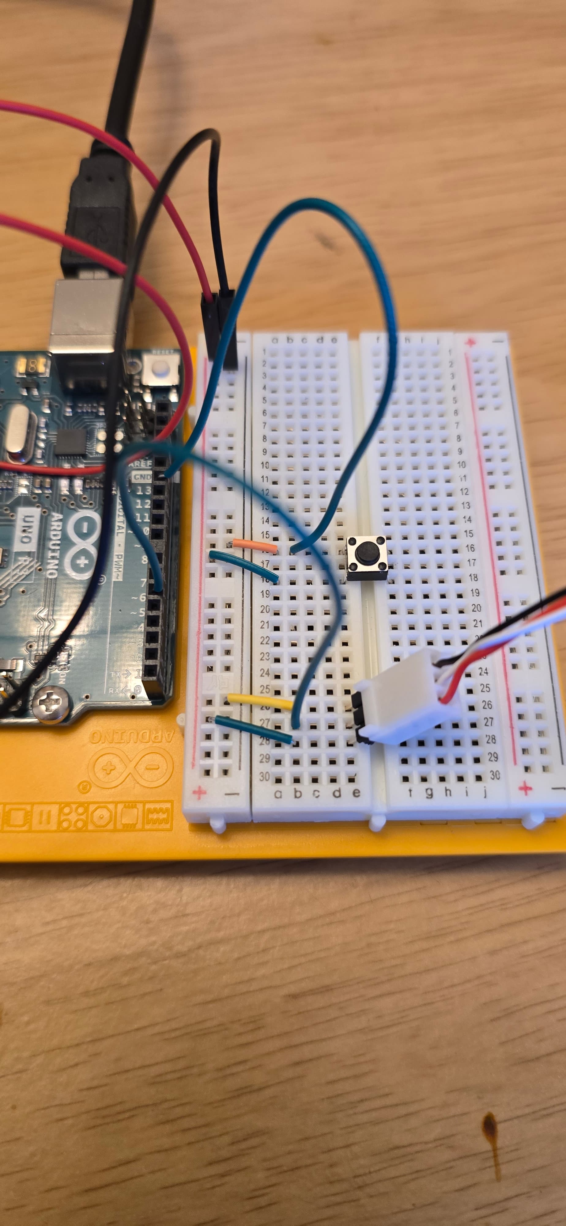
Difficult to tell from image that shows half of the circuit, but looks like your button is shorting 5V to GND?
I haven't checked your code or assembly, but I can anticipate a possible problem.
I couldn't confirm, but you are powering your servo (+V of the servo) from your Arduino Uno.
If so, I can guess that it won't work properly, because the servo draws much more current than the Arduino can provide.
After all, an Arduino is not a power supply.
Use an external power supply to power your servo.
And don't forget to connect the GND of this external power supply to the GND of the Arduino.
Please don't post images of code
Please follow the advice given in the link below when posting code, in particular the section entitled 'Posting code and common code problems'
Use code tags (the < CODE/ > icon above the compose window) to make it easier to read and copy for examination
https://forum.arduino.cc/t/how-to-get-the-best-out-of-this-forum
Please post your full sketch, using code tags when you do
Posting your code using code tags prevents parts of it being interpreted as HTML coding and makes it easier to copy for examination
In my experience the easiest way to tidy up the code and add the code tags is as follows
Start by tidying up your code by using Tools/Auto Format in the IDE to make it easier to read. Then use Edit/Copy for Forum and paste what was copied in a new reply. Code tags will have been added to the code to make it easy to read in the forum thus making it easier to provide help.
It is also helpful to post error messages in code tags as it makes it easier to scroll through them and copy them for examination
Your wiring photo is not very clear, but it seems that the button is wired so that if you press it, you will create a short circuit between +5V and ground (tip: do not press the button!).
Edited to Add:
I think you need a pull-down resistor between ground and where the button and the blue wire (from pin 12) are joined. In other words, replace the orange wire (currently between row 16 and the "-" strip) with a suitably sized resistor.
Ok will do this in future, thanks ![]()
The servo worked drawing power from the arduino, when i wired it up according to project 5 in the starter kit - although that cicuit did incorporate 2 capacitors, not sure if this makes a difference.
And i did press the button a few times, hopefully not done any damage.
Any idea on how i should change my current circuit to make it work, so the button makes the servo move as in the code? Explained in very simple terms ![]()
![]()
Apologies for my ignorance, I know this is basic stuff ha
See the edit I added to my previous response:
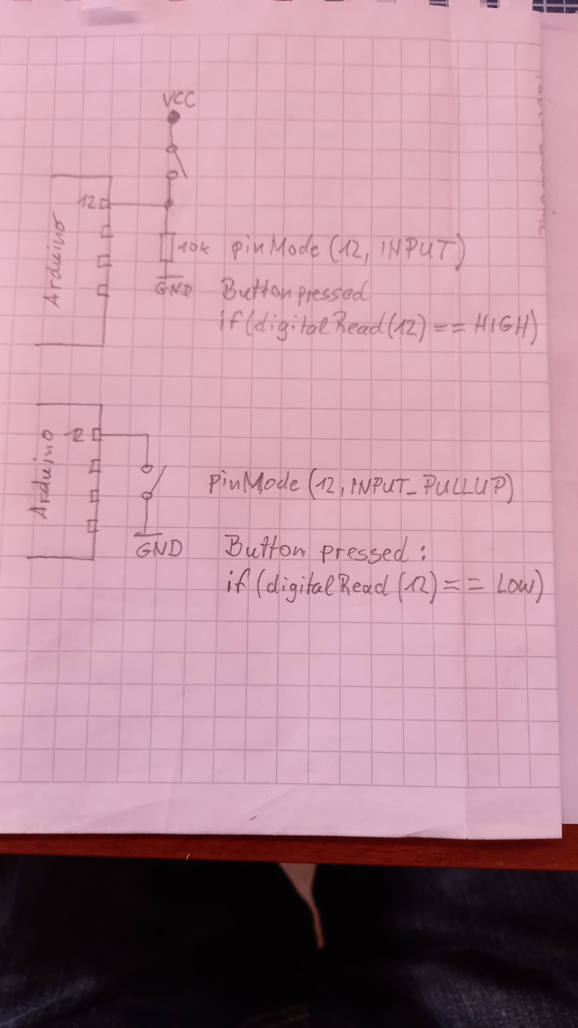
Alternatively, for a solution without resistors, see this example:
https://docs.arduino.cc/built-in-examples/digital/InputPullupSerial/
(switch pin 2 in the example for pin 12 in your setup).
If you use this method, you will have change the if statement in your loop function to test for reading == LOW instead of reading == HIGH.
You can go back to Project #2 and Project #9 in the Projects Book for examples of how to properly wire a momentary closure switch using a pull-down resistor.
Great, thank you for these replies. I got sidetracked with other things, but have now got the circuit to work ![]()
And have just bought an arduino r4 wifi, so trying to get to grips with the cloud system at the moment.