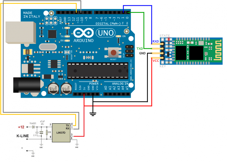
Bike interface OBD

Small update...

I decided to look at the K-line signal on the oscilloscope:

After replacing the 100nF capacitor with 10nF it looked like this:

That made the difference! I got the correct response from the ECU:

It only works when the motor is not running, so reading rpm is a bit boring for now.

Hi junkienl,

Nice that you found the issue.
Why does it only work with engine not running?

Due to the fact I cannot see your current code, but see what you wrote about the initialization:

Kawasaki & Suzuki got exactly 3 (more or less big) differences:

  • ECU Addres: 0x11 / 0x28 Kawasaki 0x12 Suzuki
  • Kawasaki requires a "Start Diagnostic Session"-Message
  • Kawa requires one message per value, Suzuki sends them all at once

What you did right is part 1. But you (might) missed the second:

// Start Communication is a single byte "0x81" packet.
81 11 F1 81 04
// Response should be 3 bytes: 0xC1 0xEA 0x8F
//243 & 143 (Explaines supported Header type: Source, Target, Length & Checksum)
// Success, so send the Start Diag frame
// 2 bytes: 0x10 0x80
80 11 F1 02 10 80 14

The documentations says you can stop the diagnostic session, but in my findings this does not work!
Just quit the communication, like you started it, but with 0x82
81 11 F1 82 05

The Kawasaki will definitely send you all the values with a running engine, then!

PS: Btw, this thread is about Suzuki. The Kawasaki thread is here :slight_smile:

Hi TriB,

Thank you for replying. I saw the other thread, but I did not notice the Suzuki/Kawasaki distinction. I just tossed a coin and ended up here... :slight_smile:

My problem seems to be a power issue. I got some rpm readings, but only after the warm up time when the rpm drops to normal idle. Just after startup the voltage is about 14,5 V. This is the handshake that I witnessed:

TX: 81 11 F2 81 05 – start communication
RX: 80 F2 11 03 C1 EA 8F C0 – accepted
TX: 80 11 F2 02 10 80 15 – start diagnostic
RX: 80 F2 11 02 50 80 55 – accepted

Revving the engine slightly makes the connection fail again. This is what I have tried so far:

1st test: Power the L9637D directly from the diagnostic plug.

2nd test: Power the L9637D through a L7812 voltage regulator. (I don’t have a better regulator available. This one has a voltage drop of 1,7 V.)

For both cases:
-Works when engine off.
-Works when engine idling or slightly revving.
-Does not work for revving >2500rpm

I am not sure how to fix this… I will look through the threads and see what others have done.

The most common issue is in deed, that voltage drops or peaks affect the Arduino.
On my first "design" it happened, that the connection stopped after about 10 Minutes. But it ran for hours, connected to my ECU-Emulator, which simulated the ECU via USB.

But I´m not an electronics pro. A friend of mine did the PCB design. So I cannot really tell you, how to create a reliable power supply :-[

I've only skimmed these pages briefly but I was in the middle of doing the ground work for something like this on Kawasaki ninja zx10r 2004
I had previously strayed on an 07 plate that was unfortunately stollen last year...

I had very small success with the 07 but I used a cheap elm odbII adapter, it read commands mad the Bluetooth software actually picked it up briefly, anyway that said.

Would anybody have clear cut instructions of the simplest way to do this? I'm after building my own mini dash and diagnostics, possibly camera overlay data unsure yet, I did build the basic circuit as I said earlier using L9637D but I couldn't get it working, struggled with getting the pins right I couldn't get any read out at all

Hi uronour,

there is another Kawasaki specific thread.
And this is more specific to transfer OBD compatible data to a camera or something.

Due to the KDS Software you own a ZX10R C1? This is supported for KDS2, which is good 8)
AFAIK you have the same connector like me. So pinout should not be a problem.

There are two ways to archive a connection:

  • Creating an own device, using a L9637D with an Arduino (Or standalone ATmega)
  • Using an expensive ELM327 compatible diagnostic adapter

No. 1 is the preferred and more flexible way.
No. 2 will not work with cheap china clones, which are not as configurable as original ones. Also most of them does not support the K-Line properly. Just the licenses for an official ELM327 is about 50 € / $. Just to have an idea about how to figure out a china clone.
And additionally to that, you have to reconfigure the adapter every time you want to use it, via AT-Commands.
Which means in the end, you have to be responsible to talk to it via bluetooth, yourself!
Or use at least an application, which is capable of using startup commands, such as RaceChrono.

How to reconfigure another device can be seen here.

hi, I just released a library that can use both the KDS (kawasaki) and the SDS (suzuki): KWP2000

I am looking for people with honda/yamaha because i can bring the library also to these bikes!

aster94:
I am looking for people with honda/yamaha because i can bring the library also to these bikes!

After looking into some data from honda, I stopped my approach to get a "all in one" solution.
There is no header, nothing similar to Suzuki or Kawasaki. This would mean to write a completely new solution, and use it parallel.
I still have enough work to get the diagnostic things from Kawa & Suzi OBD2 compatible and more stable. So I removed Honda from my list.
But if I can help you in any way, let me know :slight_smile:

TriB:
After looking into some data from honda, I stopped my approach to get a "all in one" solution.
There is no header, nothing similar to Suzuki or Kawasaki. This would mean to write a completely new solution, and use it parallel.
I still have enough work to get the diagnostic things from Kawa & Suzi OBD2 compatible and more stable. So I removed Honda from my list.
But if I can help you in any way, let me know :slight_smile:

Thanks Trib :smiley:

actually all i know about honda and yamaha cames from these few lines (which i found in this forum or on ecu hacking):

As far as I could understand the YDS (Yamaha Diagnostic Protocol) protocol, it is close to the Honda protocol.
There are no sender-/receiver-addresses or header information. Just the checksum at the end.
You initialize the diagnostic mode by sending 0x80 and from then on you can just submit 0x02 and it gives you:
Rpm, Speed, Error, Gear & Checksum.

From these few lines it is not clear if the start sequence is needed (i mean the 25ms low and then 25ms high)

then it looks that someone should just send: 0x80 and checksum
and at the end send: 0x02 and cheksum

Do you have more info?

I still have enough work to get the diagnostic things from Kawa & Suzi OBD2 compatible and more stable.

If you need any help tell me!

Hello again! It's getting warmer out so I've started working on this again. Last update I had decoded which bytes from 0x21 08 line up to what on my 2013 Suzuki GSXR1000 and compared to Aster's, TriB's and O5i's PIDs and formulas.

The next step for me was to enter equations into the Racechrono app since I already owned a OBDLink MX for car diagnostics so I figured that I would use that rather than build my own. I've been in discussion with AOL (Racechrono developer) and we are working on an updated version as we speak!

Unfortunately. It appears as if some of the equations will need modification. Suzuki seems to change something with every model since some of the equations are not even close to the ones suggested by Aster, TriB and O5i which is disappointing. I'll set out soon on the road with a camera on my gauges to then compare to the Racechrono data to see how far off they are and see if I can get better equations where needed.

On to my current question

I would like to record tire pressures and tire temperatures and I need something that will connect through bluetooth. Does anyone here already do that? I have no issue buying and building a circuit to make this happen if needed.

I would prefer an internal sensor similar to a car, however, I have seen lots of screw in types like the FOBO Bike 2. My issue with that is that it is external and I would want it installed for balancing which shops won't want to do (since they have to remove and reinstall (with the safety clips) and it uses a separate app. I want to integrate this into Racechrono.

A question as well. How different would internal tire temperatures be from external? Would their be much of a difference? I've seen examples of people installing external sensors in the mud flaps for temperature. My issue with that is that those would restrict tire warmers from going on. So I would prefer and internal sensor which does both Pressure and Temperatures.

Thoughts on how to do this???

Thanks!

Hmm, I got a demo-file from a newer GsxR1000 and my own Gsx-R600 (2006).
Both are quite similar :roll_eyes:
Just give us some examples, so we might find something.

What´s wrong with aol´s current solution? I worked it out with him in the past... But didn´t used it productive, due to my cameras, which are OBD2 compatible.

I got a tire temperature and pressure system, which replaces the valve cap.
This is rubbish! The temp is far from reliable! And the pressure mostly "okay". It was submitted by a 433mhz protocol, which I didn´t found out. But my attempts have been not very intense.
I guess it´s much better to have it inside of the tire! And bluetooth is more standard, so you might have an easier access.
Currently, I measure once or twice a day on a racetrack. With brand new tires more often. So I throw them away :smiling_imp:

Hey TriB,

I was asking some questions on racechronos forum and Aol realized that there might be an issue for non obdII compliant vehicles using custom pids. He rewrote some code and the test version includes a new setting to switch on for bikes like mine.

Then I ran some tests for him and sent the data. It appears to be working great! Still formula issues, however, I plan on starting work on those in the next few weeks. Need to put water in radiator and fairings on and will hit the road to test! I'll post my results here and hopefully we can solve my eqn issues.

As for tire temps, AOL already supports RejsaRubber which is a diy sensor! So I'll most likely be doing that. Need to check clearances but there is a very good write up here:

As for pressure and internal temps, I found an internal Bluetooth sensor that I'm going to try. It's by Blu technology.

http://techbyblu.com/phone/index.html

I'll reverse eng the code and hopefully be able to add to Racechrono.

Earendil86:
A question as well. How different would internal tire temperatures be from external? Would their be much of a difference? I've seen examples of people installing external sensors in the mud flaps for temperature. My issue with that is that those would restrict tire warmers from going on. So I would prefer and internal sensor which does both Pressure and Temperatures.

Thoughts on how to do this???

Thanks!

Heya --

A couple of things: I've been logging tire data starting last year for track/race. Honestly, the middle of the tire is totally uninteresting -- most ppl put IR sensors under the rear hugger and front fender -- two per wheel, close to the outside edge of the tire. There is enough room to get warmers on. I use sensors made by Aim, and they are basic 0..5V output in a durable package.

If you use a needle type pyrometer after you come in from a session, you can start to get a sense of the difference between logged IR surface temps and the rubber close to tire core.

If you are using 'slicks', logging tire temps is useful at the track, especially if you have cold/hot alarms configured on your dash. Slicks have a pretty tight useful operation range, and you can save yourself some drama and tire destruction if you warn yourself if out of range. Then, you can usually adjust temperature by raising/lowering temp.

O

Hey all,

I've seen posts by many of you. Thanks

So, I am trying to hack R6 Kline. I sniffed data with a logic analyzer, and I think I have enough understanding to try tests. As we all know, there's an initialization needed prior to regular communication. The stream looks simple (although interpretation might need a little coffee-time), but the init phase looks non-standard -- not KWP slow/fast.

First pass, I am writing two sketches -- one proxy for OEM Dash (which I want to replace) and one proxy for ECU replies. I'll get them working with each other, and then I can swap in and out to real HW. In the initialization handshake, microsecond timing is required, and I figure it's easiest to just bit-bang.

I've been writing code for some years, but I am new to AVR/Arduino. Both sketches use timers & interrupts -- but i've been getting weird behavior for a couple of days -- interrupts are firing before expected. I'm still at it, but I might post some code and ask for second-eyes if i stay stuck.

O

hi Guys! I'm found this work and I need to say you all are awesome! Great work at all about K-line!

I'm with a L9637D, a arduino nano and some stuff...

My project is a K-line but is not a reader... And I'm here calling for help:

The issue:

I have a honda s2000 cluster 2007 (this is a k-line cluster) and not the entire s2000 honda (saddly :slight_smile: ) and make this cluster runing in a old honda car.

The Goal:

All cluster work fine and some convertions about VSS or other signals are a simple "analog to digital converter" and this working good and shining but the ECT (engine cooling temperature) is over the K-line...

Without the ECU, I can't sniff codes and try to move the ECT bars...

But in google I,ve found some information (from TriB project) crossing some information about a S2000 tunners:

Brake pedal pressure (ID = 106 byte 3) streams at about 150 frames per second.
Throttle pedal position (ID=170 byte 1) streams at about 100 frames per second.
Steering Wheel Position (ID=198 bytes 1 & 2) and Lateral Accelleration (ID=198 byte 3) stream at about 100 frames per second.
Engine Coolant Temp (ID = 300 byte 1), Ambient Temp (ID = 300 byte 2), Engine RPM (ID = 300 bytes 5 & 6) stream at about 100 frames per second.
Wheel Speed (ID = 448 bytes 5 & 6) stream at about 60 frames per second.

You guys work hard in k-line decoder and I need to create the exactly messagens to send to the cluster... (maybe someone here can take me a light) and with the upper information "Engine Coolant Temp (ID = 300 byte 1)" maybe I can do that!

Ok All fine and clarify to all about what I do and if someone can help to guide me... my doubts:

(I'm attach 2 versions of L9637D schem but these 2 are readers and with BT, I don't need BT, only serial to debug and nothing more)

  • 10400 Baud? Makes me sense use this for "almost a default ecu" format message sender (to the cluster waiting the messages)
  • someone can show me a example exact to "Engine Coolant Temp (ID = 300 byte 1)" hex sender? Is not clear to me how I create a test message with this information in hex (all converison from analog I can do after confirm the cluster read the messages)

Thank you all, I'm not post any code to don't "over information" (and wrong) about this

Hello!
I have a Suzuki Bandit 1250 and thanks to this forum, I made a gear indicator.

You can see how it looks here: Suzuki GSF 1250 Бортовой компьютер - YouTube

Now, I want to add fuel rate to the indicator. Please help me, how can I calculate this?

I found these PIDs:

32 High Cylinder 1 injection time (ms)
33 Low
34 High Cylinder 2 injection time (ms)
35 Low
36 High Cylinder 3 injection time (ms)
37 Low
38 High Cylinder 4 injection time (ms)
39 Low

Is it real injection time? What is the formula for calculating in ms?

Thanks!

rubensx:
All cluster work fine and some convertions about VSS or other signals are a simple "analog to digital converter" and this working good and shining but the ECT (engine cooling temperature) is over the K-line...

Without the ECU, I can't sniff codes and try to move the ECT bars...

Hi,
that sounds tough! You want to emulate an ECU to change an analog value (from a temperature sensor) to a k-line signal, which provides a gauge or something?
Did I understand that right?
For me it sounds a bit strange, at the first place. Because k-line is more or less not a common communication protocol between the components, because it is quite slow.

For Suzuki and Kawasaki we have 10417 baud and a protocol which consists out of:

  • Format byte (always 0x80 except of initial message 0x81)
  • Receiver address (0x11)
  • Sender address (0xF1)
  • Length
  • Service idendtifier
  • Protocol identifier
  • Data
  • Checksum

This is part of the KWP2000 / ISO 14320 protocol.
How the service identifier (SID) and protocol identifier (PID) work, is different from manufacturer to manufacturer.

So we all have no clue, how it might work for your S2000.
What I do know: Honda Motorcycles does not rely on that kind of protocol. The don´t have a Header (Format + Receiver + Sender) and I still did not completely understood it.

If you might have some data, we can take a look, but don´t promise anything. Sorry :confused:

Ser_Ov:
I found these PIDs:

32 High Cylinder 1 injection time (ms)
33 Low
34 High Cylinder 2 injection time (ms)
35 Low
36 High Cylinder 3 injection time (ms)
37 Low
38 High Cylinder 4 injection time (ms)
39 Low

Is it real injection time? What is the formula for calculating in ms?

Hi,

yes, that will show you the ms per cylinder.
But not every bike will have that!
AFAIK you just have to add both bytes (A * 256 + B)

0x05 0x4C
5 * 256 + 76
1356 ms

at ~ 1200rpm
Good luck :slight_smile:

TriB:
Hi,
that sounds tough! You want to emulate an ECU to change an analog value (from a temperature sensor) to a k-line signal, which provides a gauge or something?
Did I understand that right?
For me it sounds a bit strange, at the first place. Because k-line is more or less not a common communication protocol between the components, because it is quite slow.

For Suzuki and Kawasaki we have 10417 baud and a protocol which consists out of:

  • Format byte (always 0x80 except of initial message 0x81)
  • Receiver address (0x11)
  • Sender address (0xF1)
  • Length
  • Service idendtifier
  • Protocol identifier
  • Data
  • Checksum

This is part of the KWP2000 / ISO 14320 protocol.
How the service identifier (SID) and protocol identifier (PID) work, is different from manufacturer to manufacturer.

So we all have no clue, how it might work for your S2000.
What I do know: Honda Motorcycles does not rely on that kind of protocol. The don´t have a Header (Format + Receiver + Sender) and I still did not completely understood it.

If you might have some data, we can take a look, but don´t promise anything. Sorry :confused:

Thankyou for your help and attention TriB...

In attach I put a image from a Honda s2000 cluster!
Yes, all cluster work fine, some features (like a CHECK ENGINE light and other simple lights) I've make work in a civic EJ1 1995! These simple alerts don't need the CAN or K-line Protocol!

But this specific version (after 2006) the S2000 has a ambient temperature, engine coolant temp and oil temp... This parameters are calculated by ECU in delta and the result is showing in the cluster (Oil life and ECT gauge).

The ECT gauge only moves by a k-line/CAN messages and not a simple analog signal or digital pulse signal (like the tachometer and VSS in this case are digital pulse). This digital pulses I create "analog to digital" conversion with arduino pro micro and work fine.

Back to ECT, I started my research with a MCP2515 shield and tying to conect to the cluster or "read" somenthing... and "don't work".

With more deeply google research I've found the information: Honda S2000 - 2007 year are K-line and not CAN... And... This moves-me to found you and some information...

In a S2000 Forum, I've found th information from a datalogger scanner called "racelog" (and this scanner can learn k-line and PIDs from ECU to use information in races logger etc...) - Engine Coolant Temp (ID = 300 byte 1), Ambient Temp (ID = 300 byte 2),

And my doubt are "how to create this message above to your code and library can be sended to the cluster...

With a L9637D + arduino Nano I'm create this board (in another image). I'll pretend test it

I strat from this code (completly clean still untouched):

nclude "Arduino.h"
// Be sure that the AltSoftSerial library is available, download it from http://www.pjrc.com/teensy/td_libs_AltSoftSerial.html"
#include "AltSoftSerial.h"


#include "OBD9141.h"

#define RX_PIN 2  // connect to transceiver Rx
#define TX_PIN 3  // connect to transceiver Tx
//#define EN_PIN 10  //  pin will be set high (connect to EN pin of SN65HVDA100)

AltSoftSerial altSerial;

OBD9141 obd;


void setup(){
    Serial.begin(9600);
altSerial.begin(10400);
    delay(2000);
  //  pinMode(EN_PIN, OUTPUT);
  //  digitalWrite(EN_PIN, HIGH); // enable the transceiver IC.

    obd.begin(altSerial, RX_PIN, TX_PIN);

}
    
void loop(){
    Serial.println("Looping");

    bool init_success =  obd.init();
    Serial.print("init_success:");
    Serial.println(init_success);

   // init_success = true;
    // Uncomment this line if you use the simulator to force the init to be
    // interpreted as successful. With an actual ECU; be sure that the init is 
    // succesful before trying to request PID's.

    if (init_success){
        bool res;
        while(1){
            res = obd.getCurrentPID(0x11, 1);
            if (res){
                altSerial.print("Result 0x11 (throttle): ");
                altSerial.println(obd.readUint8());
            }
            
            res = obd.getCurrentPID(0x0C, 2);
            if (res){
                Serial.print("Result 0x0C (RPM): ");
                Serial.println(obd.readUint16()/4);
            }


            res = obd.getCurrentPID(0x0D, 1);
            if (res){
                Serial.print("Result 0x0D (speed): ");
                Serial.println(obd.readUint8());
            }
            Serial.println();

            delay(200);
        }
    }
    delay(3000);
}

This code makes sense to me by the 9600 baud to my computer can show me what are sended and a altserial can up the 10400baud to the kline...

but I need some simple at now... send the message "ID = 300 byte 1" in hex to test if the ECT gauge restpind...

The time to respond in gauge are not much important, the ECT rise slow and the information is not much precise in bars...

maybe I make this more clear now...

thank you again

Hello rubensx,

alright! If you cannot get some further information about the exact protocol, you have to sniff it yourself.
That´s the solution how all of this started:
Someone got an external gear display, which was connected to the diagnostic port.
Then he took an arduino and put it in between, to pass all the data untouched through. But off course the data was also written onto an sd card!

That´s how the Kawasaki and the Suzuki solution founded. Afterwards, there have been several 3rd party diagnostic tools, which were analysed.

Long story short: If you can manage to find a working S2000, where you can get into the communication between those parts, try to sniff them.
Otherwise you have to find someone, who already did this.

I can just hardly guess, but the difference between Suzuki & Kawasaki is quite big. Honda even more and nobody knows, if the S2000 relies on that or due to it´s a car, it has a very own signature.

There are initiaization processes, the receiver id´s are different, the PID 300 is only the protocol, which SID must be requested?, afaik honda has a unique checksum calculation, etc.