When I turn on the leds they only stay on for a brief moment, then they turn off.
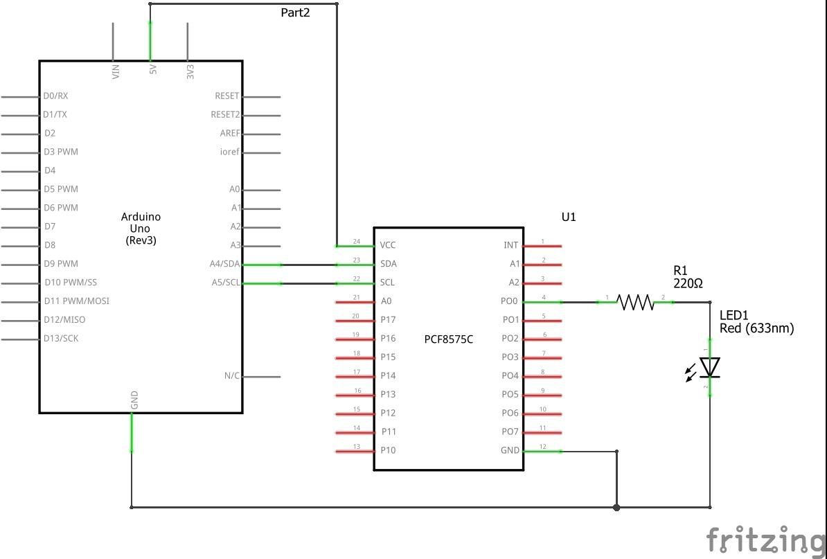
How have you connected the LEDs? Please post a schematic. With this chip, LEDs plus series resistors would be connected between Vcc and the output pin. This is because the pins can sink enough current for LEDs but cannot source very much current. If the LEDs are placed between the pins and ground, they will light only very dimly. And with your code they would light only for a very short flash and then off because that is what your code is written to do.
Please modify your post and put the code tags around your code. Read the forum guide to find out how and what other things you must and must not do. The moderators have intervened once already, so you must take care not to break other rules.
Please read the post at the start of any forum , entitled "How to use this Forum".
OR http://forum.arduino.cc/index.php/topic,148850.0.html.
Then look down to item #7 about how to post your code.
It will be formatted in a scrolling window that makes it easier to read.
Can you please post a copy of your circuit, in CAD or a picture of a hand drawn circuit in jpg, png?
jpau:
I have seen several schemes on the net, and they are connect to GND. like in this site, where the led is connected to GND: Arduino and PCF8575 I/O expander examples
Wow!
I mean, just wow!
A site called "Arduino Learning", with this article at least written by a complete fool without the electronics knowledge to comprehend a datasheet.
I have not investigated that site, but at this rate it begins to sound like another "instructables".
jpau:
I will read the rules to try to understand how it works.
OK, let me explain - and you can check the datasheet.
The PCF8574/5 uses a clever interface based on "open-drain" protocol. There is no actual "INPUT" or "OUTPUT" mode. It provides a "weak pull-up" which is the current that is lighting your LEDs dimly when they are connected to ground. If you write the register (there is really only one per 8 bits) with a zero (LOW) in a particular bit, then that pin is strongly pulled down sufficient to nicely light - up to say, 15 mA ("Absolute maximum" of 20 mA should be avoided) - a LED if it (and its resistor) are connected to Vcc (5 V).
If you at any time write the register with a "1" (HIGH) then while the I2C command is in progress, that pin is strongly pulled HIGH, resulting in a brief flash of a LED connected to ground as you have seen.
50mA. (But there is a 100mA total limit for the chip, so only 5~6mA per pin if 16 LEDs attached). The 20mA limit is something to do with protection diodes on the pin, I think.
Paul__B:
If you at any time write the register with a "1" (HIGH) then while the I2C command is in progress, that pin is strongly pulled HIGH, resulting in a brief flash of a LED connected to ground as you have seen.
Interesting, what page does it say that on? I was putting the brief flash down to the OP's code, which sets all pins to input and then immediately to output. With LEDs connected between the pins and ground, a brief dim flash would occur for the brief time they are set to input.
PaulRB:
50mA. (But there is a 100mA total limit for the chip, so only 5~6mA per pin if 16 LEDs attached). The 20mA limit is something to do with protection diodes on the pin, I think.
OK, mis-read that.
PaulRB:
Interesting, what page does it say that on? I was putting the brief flash down to the OP's code, which sets all pins to input and then immediately to output. With LEDs connected between the pins and ground, a brief dim flash would occur for the brief time they are set to input.
Section 8.1, page 12, second paragraph.
Well of course the port is set to input at default on power-up. In that code, you would have weak pull-ups (0.1 mA) while the Arduino is booting, a rather brief flash of 1 mA as it is written HIGH and then off.
At power on, the I/Os are high. In this mode, only a current source (IOH) to VCC is active. An additional strong pullup to VCC (IOHT) allows fast-rising edges into heavily loaded outputs. This device turns on when an output is written high and is switched off by the negative edge of SCL.