I downloaded their library (Adafruit-ST7735-Library) and flashed "graphicstest" example to my Arduino UNO board. The display is wired as follows:
VCC - 3V3
GND - GND
DIN - MOSI (11)
CLK - SCK (13)
CS - 10
DC - 8
RST - 9
BL - 3V3
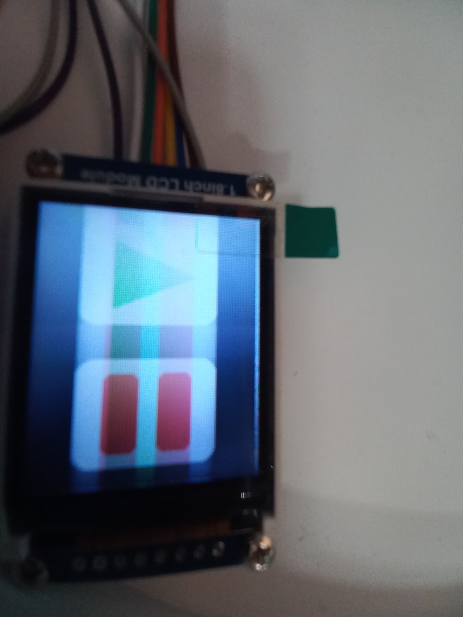
According to some tutorial I should get something like this:
The gradient of the background isn't caused by the camera, it's really visible.
Similar result comes out of default Arduino TFT library. It shows something, but it's deformed like this. I tried using my Arduino Nano too, but there was no difference. I hope that I didn't damage it in some way.
Please post a link to the actual screen that you have bought. e.g. ebay sale page.
There are many different makes of 128x160 or 132x162 TFT controllers.
And several makes of the physical TFT panel.
Most importantly, all TFT controller chips require 3.3V logic. None of them are "5V tolerant" according to their datasheets. But ST7735 seems to survive.
I suggest that you use level-shifters or resistors on the logic signals if you want to use a 5V Uno or 5V Nano.
When you use 3.3V logic, choose the appropriate "initR()" argument. e.g. your photo shows a "GREEN TAB". But it is not an Adafruit product.
I found that the Waveshare display needs some kind of offset, and it should use "GREEN TAB". It helped a bit, but still the display looks pretty much the same.
Thanks for the link. It does not matter if you buy from Poland or from Outer Mongolia. We can see that it is a Waveshare product with documentation https://www.waveshare.com/wiki/1.8inch_LCD_Module
Regarding Logic levels. This is from the datasheet:
and this is from the schematic
So you can see that there is no way that you can use 5V logic. However simple series resistors will probably be "safe".
I strongly suggest that you use 3.3V logic. e.g. Zero, Due, STM32, RaspberryPi.
If you must use 5V logic do it via resistors, level shifters.
Since you clearly have a Waveshare item I would be confident it is ST7735S.
Just use 3.3V logic and try all the different initR() values.
David.
p.s. please measure R1 with a DMM. I would expect 100R and not 10K.
I found a bunch of level shifters laying around, but it seems like the screen died completly. I'll try to get it to work tomorrow, but I doubt it's still working. It looks like the logic level, according to the datasheet, is up to 4.6V, so I'm suprised that 5V damaged it. I need to be more carefull next time. Thanks for help.
And yes, they have an error in the shematic. The resistor is 10 ohms, not 10K.
Go on. You have been a member for 7 years !!
I don't know what brand of Ohms Law could produce 500mA
Typical white LEDs used in backlights have a forward voltage of 2.8V - 3.0V.
So a 10R series resistor in a 3.3V supply will mean 0.5V / 10R = 50mA vs 0.3V / 10R = 30mA.
In practice Q1 will probably saturate at 0.1V. meaning 40mA vs 20mA
Well, the good thing is that my screen isn't burned out. It works with my RPI without a problem. I have no idea why it's not working with Arduino. I'm going to rewire everything and try again.
Success! I got it working. It turned out that the 5V logic level was the problem. And with Waveshare, I needed to use "GREEN TAB" initializer. Thank you for help.
There is a recent thread about Waveshare 1.5 inch OLED. The Waveshare schematic shows 3.3V operation but docs say you can connect directly to 5V Uno logic.
I am surprised. I would have expected Waveshare to either provide level-shifters or just say "unsuitable for 5V Uno"