Your topic does not indicate a problem with IDE 1.x and therefore has been moved to a more suitable location on the forum.
How do you know that LCD.init() works?
Does it not show "ABC"? Does it not blink?
What is the display that you're using? Is it a 3.3V display? Or a 5V display? That might be a reason why it does not work.
===
Please learn to use code tags properly; you were supposed to replace Előformázott szöveg with the content of your file. The code tags (opening ``` and closing ````) also need to be on their own lines.
Thanks for your advises!
As I have seen, the display settings were effective, but the print command has no effect. My display module is an 5 V model, but the pull up resistors are tied to 3,3 V
I am not going to spend time with your word salad you call code. Post it properly using code tags, that was explained if you read the directions on how to use this forum. I expect it will be a simple answer. Also post an annotated schematic, that always helps.
//YWROBOT
//Compatible with the Arduino IDE 1.0
//Library version:1.1
#include <Wire.h>
#include <LiquidCrystal_I2C.h>

LiquidCrystal_I2C lcd(0x27,16, 2); // set the LCD address to 0x27 for a 16 char 2 line display

void setup() {
  Wire.begin(10, 8);
  lcd.init(); // initialize the lcd
  lcd.backlight();
  lcd.backlight();
  lcd.noCursor();
  lcd.blink_off();
  lcd.autoscroll();
}
void loop() {
  lcd.setCursor(0,0);
  lcd.print("ABC"); //print does not work
  delay(1000);
  lcd.clear() ;
}
There you go, @gilshultz, hope that helps. I wonder if the code comment about IDE 1.0 compatibility is relevant, given his use of 2.3.6?
Thanks for your advise! The SDA, SCL lines were watched on oscilloscope.
The lines were active both after the lcd.init() command and the print() too, but the print() had no effect at all. Should I go back to IDE 1.0? I am newby at C++ and first I need working sample headers to include for study. A "HelloWorld" like app. seems a good tool.
IDE 2.3.6 ; lcd.init() works, lcd.print() command does not work, I2C pins are busy on oscilloscope. The second 'delay(1000)' did not help.
the result was: A blinking cursor in position (0,0) and 1 sec later in (3,0).
I think the print() command works false.
"'//YWROBOT
//Compatible with the Arduino IDE 1.0
//Library version:1.1
#include <Wire.h>
#include <LiquidCrystal_I2C.h>

LiquidCrystal_I2C lcd(0x27,16, 2);  // set the LCD address to 0x27 for a 16 chars and 2 line display

void setup()
{

Wire.begin(10, 8);
lcd.init();                      // initialize the lcd
lcd.backlight();

lcd.backlight();
lcd.noCursor();
lcd.blink_off();
lcd.autoscroll();

}
void loop()
{
lcd.setCursor(0,0);
lcd.print("ABC");  //print does not work
delay(1000);
lcd.clear() ;
delay(1000);
}'"
Hi!
Non of the built in libraries handles correctly the “print() “ command. Initialisation looks correct: the default ligting single row diappears as seen in the other environments, the sda and scl lines are busy on my oscilloscope, if I place the print(“ABC”) command in a loop, but nothing displayed.
I have tried some custom libraries too without success.
(Open the link and scroll down to "Use Different I2C Pins with ESP32 (change default I2C pins)")
However, if you’re using libraries to communicate with those sensors, this might not work and it might be a bit tricky to select other pins. That happens because those libraries might overwrite your pins if you don’t pass your own Wire instance when initializing the library.
You could try to use the standard sda/scl pins of your board first.
If it still doesn't work there may be another problem. If it works you have to modify your code in accordance to the example shown in the link (create a TwoWire instance, set its parameters and use this instance in Wire.begin()).
The board I am using is the YD ESP32-S3-N16R8 dev. board. Clone of ESP32-S3 C1. Pinning the same, with slightly different layout.
2)About the firmware I do not have details.
3)The display has a PCF8574T based backpack board, soldered direct on the 16*2 LCD module.
Address is 0x27 (all the three address bits are open).
5)The module has standard LCD controller, I was using it for many years in my PIC 16F628 based projects. Iwrote an LCD setup sw.- module in assembly, together with my own I2C emulation, both worked fine. Now I decided to try C++ instead assembly, and bought this ESP32, and begun with a Hello World trial. I know, most of the work is done by the libraries and the compiler in the background. This the reason why I am looking for a library already tested on the HW. I have.
At he moment as I see, the initialization command acts well. Changed the default settings , as prescribed in the LCD catalogue. The print () command although causes some bytes running on the I2C bus, but do not write any characters to the LCD. (My oscilloscope watches the SCL and SDA lines permanently.) Thats’ it..
Peter
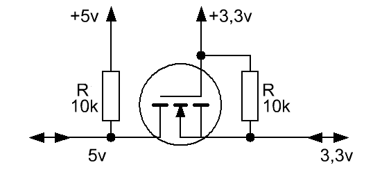
The LCD runs on 5V. The I2C driver ( PCF8574 ) has open drain bus driver, and CMOS logic level input. Assume, the ESP32S3 does the same as master. So I have tied the pull up resistors to 3,3 V.
A quick read of the datasheet reveals that the minimum Vih for the PCF8574 is 0.7V * Vcc. So if it's powered by 5V, it wants to see a minimum 3.5V on SDA and SCL to register a HIGH. What voltage are you seeing on those inputs?