Use the IDE autoformat tool (ctrl-t or Tools, Auto format) before posting code in code tags.
Please post a schematic. Written descriptions are always more ambiguous than a drawing. Hand drawn, photographed and posted is fine. Include all pin names/numbers, components, their part numbers and/or values and power supplies.
It is unlikely that you have burnt your Arduino Mega 2560 by simply using the built-in LED on pin 13. The LED on pin 13 is connected to a current-limiting resistor and should not draw enough current to damage the board.
However, it is possible that the LED itself has failed or that the current-limiting resistor has been damaged, causing the LED to burn out. This can happen if the LED is subjected to too much current or if there is a short circuit on the board.
To troubleshoot the issue, you can try the following:
Check the LED: Use a multimeter to check the LED on pin 13. If the LED has failed, you can replace it with a new one.
Check the current-limiting resistor: Use a multimeter to check the resistance of the current-limiting resistor. If the resistance is not within its expected range, you may need to replace the resistor.
Check for shorts: Inspect the board for any signs of a short circuit. Look for damaged components or traces, and use a multimeter to check for continuity between different parts of the board.
If you are still unsure what the problem is, you may want to try using a different Arduino Mega 2560 board or contacting the manufacturer for support.
Well, the problem isn't really the LED itself, for me it's an indicator that there is something not going entirely well within the board.
When I attach a potentiometer and a servo, combined with a working code, the servo eventually stops working, because there seems to be no power supply.
Also, as the brightness of the LED is decreasing, the servo goes slower second by second, and eventually just stops.
During today's morning it was working fine, and I was testing my current code for the RC-car, with the needed components, when eventually, the situation described above was starting to take place.
If you used a high voltage battery like 11.1V 3S lipo or similar, and you connected that to the Mega's Vin pin, then powered the servo from the Mega's 5V pin, that would explain it.
An Arduino is not a power supply. If you are powering the board through the power Jack or Vin the servo is pulling so much currernt that the on board 5V regulator is probably heating up and going into shut down. If powering through USB, there is a polyfuse that will open if too much current (>500mA) is drawn.
The upshot, do not power a servo, or any other high current device, from the 5V on the Mega. Use an external supply capable of supplying the servo stall current.
Post an annotated schematic as to how you have wired it, include all connections, power, ground, and show power supplies. Links to each of the hardware items giving technical details will help. If I were to take a SWAG I would say do not connect the motors to the Arduino. If this is correct you can have done no damage but more then likely several items got fried.
In the Wokwi setup you'll see that the LED's are wired on the same pin. That is how it should be, becuase I am using bundles of LED's which I connected to each other myself. The LED's used, have a maximum power capacity of 12 Volt, and can handle up to 20 mA of current.
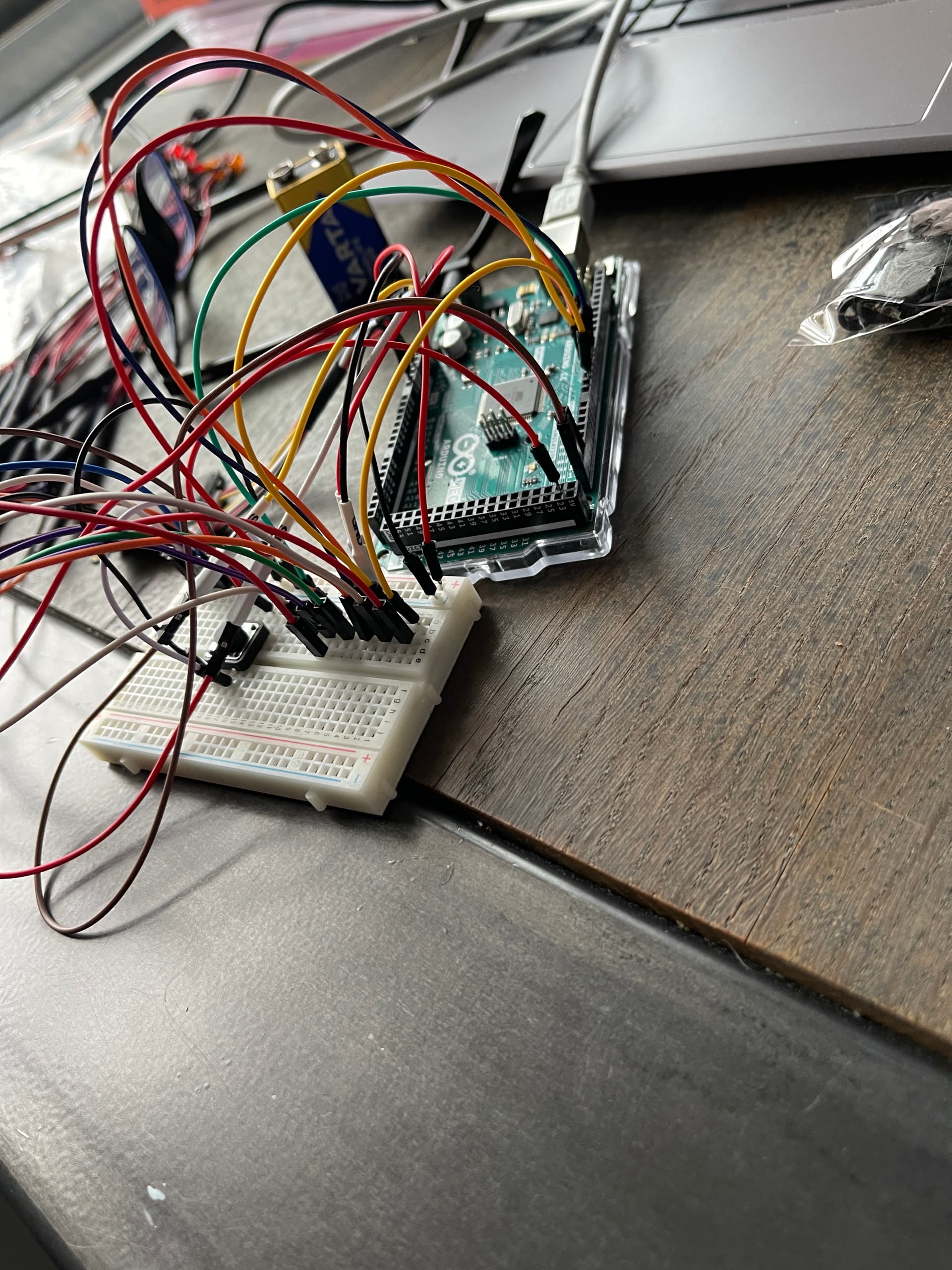
I'll leave some photos of the LED bundles I made, as well as a photo of how my Arduino board was looking when I wired everything onto it. Note that all the components I've used in the Wokwi linked above, were all connected to my Arduino board (using the breadboard) when I was testing the code.
So you were asked a number of questions about your hardware and hookup, and point to a simulator? Wherein, we can see that you've put your servo on the Arduino power, and a bunch of LEDs with no resistors(unless they have integral resistors, which might be indicated by your reference to 12V LEDs).
How's the real hardware working now? Did you disconnect the servo, as suggested?