So I will try to explain the situation as clear as possible.
First of all my sister is trying to make a drone with her team for a university project.
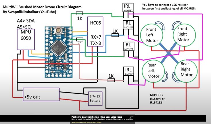
They took all parts and all the wiring from this video.
Now there is a cute problem they have faced.
To test the balance system on the drone they have to use a program called multiwii (I guess).
But when they have opened the program to test the balance system, the drone graph was going crazy.
Afterwards they have reached me to ask what is the problem.
I told them there might be a mistake with the wiring or you may have the balance system part broken.
Anyways they went to someone to test the drone on his computer.
But when he plugged the USB with the FTDI, keep in mind the drone's battery is in.
The FTDI part started burning and there was a black smoke.
When she was testing it with her laptop the battery was out.
So my question is :
Is having to power sources ( the USB and the battery ) connected at the same time made this problem.
Or was it because the FTDI part was fake or frauded as they assume.
Seems likely that the FTDI was trying to power the drone and that burnt it out or the power was wired up wrong
Suggests a bad electrical design somewhere allowing the 5v to drive the rest of the drone .
You can check the video to see the wiring.
.
After she have brought the drone to me, I checked all the wiring and there was nothing wrong with it.
(Meaning it was all the same as the wiring in the video.)
.
You can see that there is (MT3608 DC to DC step up booster modul).
This part give the power to all the parts in the drone.
So there is no way the FTDI powers up the whole drone (hopefully).
.
I didn't check the wiring all the way, but I will when I finish studying which is tomorrow.
.
But is powering the drone using both the USB and battery made this issue?
Hard to say but powering via the usb will put 5v on the 5v pin of the Arduino and so back feed other devices .
Also the wiring of the step up controller might be wrong “-“ on the output may not be the same as “0v” on the input , so you could have a short there.The only thing connected ( to both pins ) to the input of the step up controller should be the battery
As long as it does not reference any of the information given in this thread so far but is a completely different topic.
Completely incorrect. No such nonsense.
How the thread is managed is not up to you, this is a public forum but may be moderated in case of offensive behaviour. Note the explanation at the bottom:
This topic will close 6 months after the last reply.
You can see in this thread that you can not connect the outputs of 2 power supplies together.
Even you replied to that thread.
.
Once she powered it from the battery and USB the the same time the FTDI started a smoke and can clearly see that it was overheating.
.
Even the professor of the university is telling her that the reason is probably because you have plugged both in
.
So why do you think that powering them up from 2 power sources won't destroy anything?
Indeed I did reply, but the problem was of no relevance to yours.
But you have given us no information regarding how it was actually wired or what part of the adapter overheated. Without that we are completely unable to determine what the wiring mistake was.
Suspect the professor more likely indicated that the reason was probably because of a wiring mistake.
Sorry, but the fact of the matter is that if you are asking here, you clearly do not have the experience to figure out what had happened. That being the case, we also cannot trust your assertion that you believed the wiring to be perfectly correct since you did not know what sort of problems to look for. Now you might find this assessment objectionable, but unfortunately it is simply "the way it is", nothing more.
Frankly, referring us to a video and claiming the project was replicated exactly is simply unacceptable. No, I have not and will not at this point watch the video because it will not solve the problem (though there is of course, the possibility that the procedure in the video was quite wrong. YouTube makes no claim as the the veracity of anything posted. )
Because "powering them up from 2 power sources" is itself meaningless. It describes nothing. It could mean all sorts of different attempts; the fact that you mistook that other thread as being relevant illustrates exactly that (but we give you marks for undertaking research )!
You can for example, power an Arduino UNO (or a Nano and various others) by USB and "Vin" or the "Barrel jack" simultaneously. You can also power it with 5 V to the "5V" pin (and ground of course); it will not damage the Arduino but may upset the USB subsystem on the PC.
These things are commonly and perhaps easily misunderstood. The "take-home" point is that this was most likely a simple(?) wiring error but without proper forensic information, we cannot say what.
I just have a big problem with the Arduino pro mini and the FT232RL on the red base.
That one (the red) is too sensible with the touch fingers.
It's works only one time on the transfert with windows 10.
I understand it was corrupted. Then I buy a DSD-TECH-SH-U09C3-Adaptateur-FT232RL/dp/B07TS3GPQ1 and everything is now good. Just have a look with the correct wires.
Soon as I saw the circuit diagram on the video ( not the linked video I might add, but another in the series,.....had to go hunt for it) I saw there was no pull down resistor on any of the mosfets.
This could have allowed any motor to kick in and give your overload.
Did notice a little note up the top about adding these resistors (10K...gate to ground)
Wonder if anyone else saw it ...... ???