So I have been struggling for weeks now trying to get all the parts into a schematic to build my project board. After much help from this forum I was finally able to get a library containing the proper Atmel chip for Arduino Uno R3.
Now the problem is I need one for my AC to DC converter.
It is a sip package but the white papers do not specify which sip package. I have watched many tutorials on building parts in eagle but frankly they all contain obtuse language. I cannot find one that just explains in English which dimensions go where. I can't understand any of there measurements because they never seem to say where the origin of the pin grid your creating is. I seriously doubt I will be able to find this part in a library anywhere so If someone could point me to a tutorial on part layout that explains pin diameter, spacing, and pin grid origin in simple terms instead of algebra or fancy words I would appreciate it. My project is on ice until I can get this key component into the design file.
Or make a part by yourself according the drawing in the datasheet.
Eagle Control Panel -> File -> New -> Library
in Library window
Library -> Device or Package -> New ...
I would like to know how to place the holes without making that part actually. And yes I am trying to make my own part. That is the who point of this post, the how too info is not easy to understand at all.
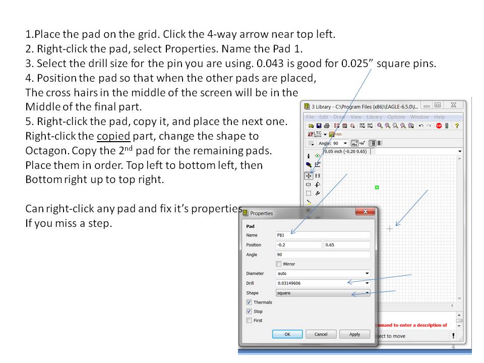
I made up a presentation on making Eagle library parts; the search feature of the forum is useless for finding it tho. I'll repost it when I get home.
For now, just use a 1x7 header from the con-lstb library, leave room around the pins for the orientation of the package you are using (SIP, or the right angle pins).
If you have the sparkfun library downloaded, you can also find a 1x7 header under M07.
Thank you for your help.I'm a newb so I couldn't find a 1x7 header if my life depended on it but I will look forward to your post. The pins on this thing are straight. No right angle.
If you open the Eagle files for a board (from Arduino, Spartkfun, Adafruit as examples, you can also use File:Export:Library for the parts in that design.
Sparkfun has Eagle tutorials, as does Adafruit:
CrossRoads:
You're welcome.
Pin 1 square pad, that goes back to before my time in board design. Really helps when you flip a board over and are debugging stuff.
Square on both sides of the board? Genius.
(Well, actually I think it might be difficult to get Eagle to make a pad different on each side.)
CrossRoads:
I've taken designs, deleted all but 1 component, and then exported to get a library for just the 1 part I was after.
So far, all the Eagle libraries I found are just text files. The information is stored in a well formatted XML. The last several times I needed to modify a library (like extracting a part) I just used a text editor.
It is my understanding that there are nice XML editors available. I suspect they would make the process even easier.
CrossRoads:
There's probably a way to export a single symbol in eagle too, I just haven't taken the time to figure it out.
It's rather non-obvious in the Eagle system.
If you want to copy a part from one library to another, first open the destination library in the library editor. Then find the part in the control panel list of libraries. Right-click and "copy to library." The part (footprint, symbol etc) appears in your destination library.
It would be nice if you could just copy a footprint instead of a complete part but there doesn't seem to be an easy method of that. Copy-paste inside the footprint editor window is possible but I find it difficult to do it cleanly.