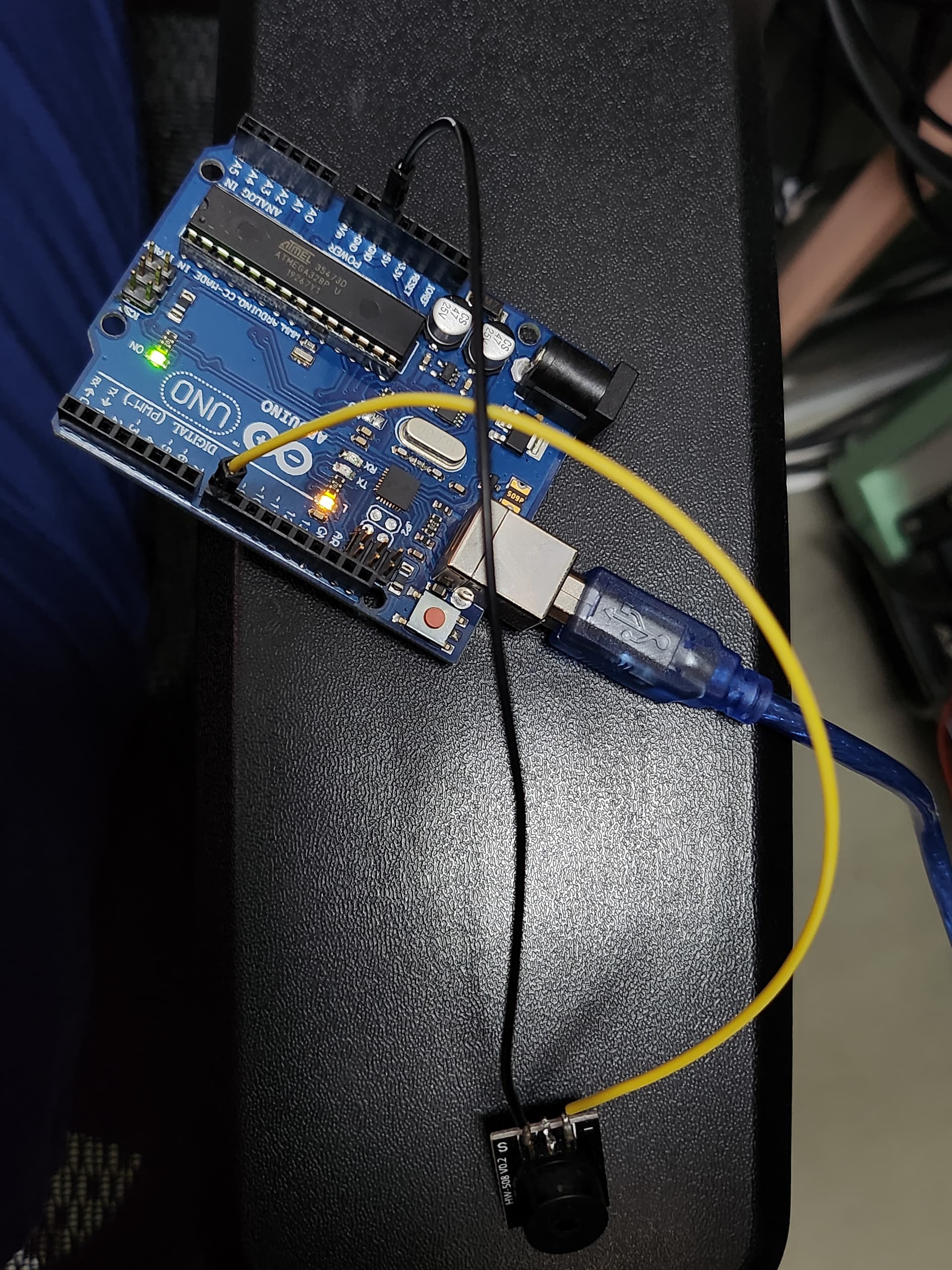
This is my current circuit. It works fine, when I connect #45 and #46, the circuit is completed so the sound is successfully generated via buzzer.
However when I disconnect #45 and #46, there is a leakage current to the buzzer, around 3V, and generates small sound.
To prevent this, I will use resistor A in between, to make sure the current leakage goes below 3V, maybe around 0~1V.
But when I only use resistor A, the sound won't be generated even when I connect #45 and #46. So I thought of applying a different resistorB between #8 and GND, and use resistorB a higher ohm compared to resistorA. I think this way, I can achieve my original goal of operating sound, and also control the leakage.
Hi @TomGeorge
Yes that thread is what I am using and the picture is the relay system, which #45 and #46 is located. I have a relay system and a program already, so when I click the button in my program, the relay's #45 and #46 will be connected. This way, the circuit is complete, and since the 5V(+) power supply is always provided, 5V will go to passive buzzer and all the way to the ground, which generates sound.
When I release the button in my program, #45 and #46 will be disconnected, so I originally hoped there would be no sound at all. But idk why, there is a leakage of around 3V in the passive buzzer when I release the button. Because of this, there is a small sound generated.
I checked the 3V flowing with the device (fluke 101 600v cat iii multimeter).
That's why I want to use the resistor.
And also, after the advices from the previous thread, I changed my circuit, and the circuit I am asking right now is in this current thread.
I can't follow your description, neither drawings.
I think it would be easier, if you just tell what you want from your circuit.
Buzzers generally don't need relay, you can drive them directly from arduino.
And relays generally don't have any leakage.
Hi, @kmin
For my experiments, it is necessary to use the relay to control on/off from buzzer. And I cannot change the part of connecting/disconnecting #45 and #46 in the relay system to control the sound.
From my first picture's circuit wiring, this is working completely fine.
But for some reason, when the #45 and #46 is disconnected, the buzzer makes a small sound.
In short, what I want from my circuit is to make sure the buzzer does not generate any sound when the #45 and #46 is disconnected.
Since there is 3V flowing to the buzzer when the #45 and #46 is disconnected, I want to use a resistor in between the buzzer and the arduino.
Also, I thought since my question is related to useage of resistor, i should post it here. Where should I move my question?
For my experiments, it's not. Actually I have newer seen one controlling buzzer with relay.
That behavior you explain sounds bad wiring or soldering or components. You should fix that. Relay output has physical gap, there can't be leakage. Also you should not control regular relay directly from arduino pin.
Oh did you test it by yourself? Thanks a lot. What I actually meant by "For my experiments" was, that I need to use the relay system for the purpose of my experiments. I am not sure about this, but your nickname sounds really Korean, and I am also Korean. I am not fluent with English, and what i meant was this: 제가 하는 실험에 저 릴레이 과정이 꼭 필요합니다, this. If you're not Korean, sorry.
Also, I don't have any other way than using resistor in my mind, because I cannot find wiring problems, and the problem consists when I use other lines, buzzers, etc.
Yes, many times.
I'm not korean and your english is very ok.
I'm not gonna help you to fry your arduino, but if you want to start from beginning, I can help.
Thanks a lot for your time. I would appreciate your help, and I would love to try it from the start.
But there are some parts that I cannot modify, such as using the relay system for regulating buzzer's on and off.
If I can keep this part, and you can help me, it would be a lot for me.
Yes it is working fine. Also works fine with my relay system (when I connect the circuit via relay system, it generates big sound with the desired frequency I set with tone() function).
One problem I want to solve is small sound still generated when the relay is off, and I suspect it is due to constant 3V flowing to the buzzer. It would be best that I can regulate between 0V and 5V with relay system, but since I don't know how, I would like to use a resistor to lower the constant 3V.
oh hi @jim-p . Thanks for your help few days ago. I tried the wiring as you adviced, but somehow the sound was not generated at all.. So I tried multiple circuits, and this one is the only one at least working..