Calculator using keypad and 2 7 segment display

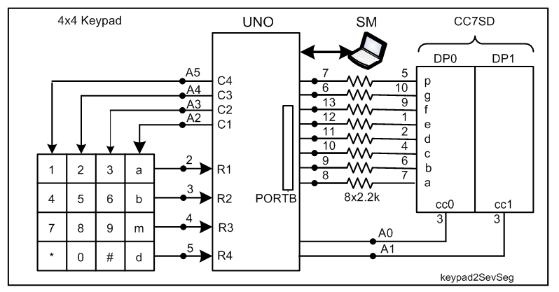
I need help with tinkercad, i need to make a one-digit calculator using 4x4 keypad, arduino uno, 2 7 segment displays

I need to figure out the whole coding and circuit

When a is pressed it is add, b for subtract, and d for displaying the answer, and it should also display negative number

example: 2B4D the number on the displays is -2

#include <Keypad.h>

unsigned const int A = 9;
unsigned const int B = 8;
unsigned const int C = 1;
unsigned const int D = 2;
unsigned const int E = 3;
unsigned const int F = 10;
unsigned const int G = 11;
unsigned const int AA = 9;
unsigned const int BB = 8;
unsigned const int FF = 10;
unsigned const int GG = 11;
unsigned const int CC = 1;
unsigned const int DD = 2;
unsigned const int EE = 3;

int first = 0;
int second = 0;
int total = 0;
int m=0;
int n=0;

char key;

void disp_number1(int x){
    int p_num=x;
    if (p_num==0){
  digitalWrite(A, HIGH);
  digitalWrite(B, HIGH);
  digitalWrite(C, HIGH);
  digitalWrite(D, HIGH);
  digitalWrite(E, HIGH);
  digitalWrite(F, HIGH);
  digitalWrite(G, LOW);
}
    else if (p_num==1){
  digitalWrite(A, LOW);
  digitalWrite(B, HIGH);
  digitalWrite(C, HIGH);
  digitalWrite(D, LOW);
  digitalWrite(E, LOW);
  digitalWrite(F, LOW);
  digitalWrite(G, LOW);
    }
    else if (p_num==2){
  digitalWrite(A, HIGH);
  digitalWrite(B, HIGH);
  digitalWrite(C, LOW);
  digitalWrite(D, HIGH);
  digitalWrite(E, HIGH);
  digitalWrite(F, LOW);
  digitalWrite(G, HIGH);
}

    else if (p_num==3) {
  digitalWrite(A, HIGH);
  digitalWrite(B, HIGH);
  digitalWrite(C, HIGH);
  digitalWrite(D, HIGH);
  digitalWrite(E, LOW);
  digitalWrite(F, LOW);
  digitalWrite(G, HIGH);
}

    else if (p_num==4){
  digitalWrite(A, LOW);
  digitalWrite(B, HIGH);
  digitalWrite(C, HIGH);
  digitalWrite(D, LOW);
  digitalWrite(E, LOW);
  digitalWrite(F, HIGH);
  digitalWrite(G, HIGH);
}

    else if (p_num==5) {
  digitalWrite(A, HIGH);
  digitalWrite(B, LOW);
  digitalWrite(C, HIGH);
  digitalWrite(D, HIGH);
  digitalWrite(E, LOW);
  digitalWrite(F, HIGH);
  digitalWrite(G, HIGH);
}

    else if (p_num==6) {
  digitalWrite(A, HIGH);
  digitalWrite(B, LOW);
  digitalWrite(C, HIGH);
  digitalWrite(D, HIGH);
  digitalWrite(E, HIGH);
  digitalWrite(F, HIGH);
  digitalWrite(G, HIGH);
}

    else if (p_num==7) {
  digitalWrite(A, HIGH);
  digitalWrite(B, HIGH);
  digitalWrite(C, HIGH);
  digitalWrite(D, LOW);
  digitalWrite(E, LOW);
  digitalWrite(F, LOW);
  digitalWrite(G, LOW);
}

    else if (p_num==8) {
  digitalWrite(A, HIGH);
  digitalWrite(B, HIGH);
  digitalWrite(C, HIGH);
  digitalWrite(D, HIGH);
  digitalWrite(E, HIGH);
  digitalWrite(F, HIGH);
  digitalWrite(G, HIGH);
}

    else if (p_num==9){
  digitalWrite(A, HIGH);
  digitalWrite(B, HIGH);
  digitalWrite(C, HIGH);
  digitalWrite(D, HIGH);
  digitalWrite(E, LOW);
  digitalWrite(F, HIGH);
  digitalWrite(G, HIGH);
}
    else if (p_num < 0){
  digitalWrite(A, LOW);
  digitalWrite(B, LOW);
  digitalWrite(C, LOW);
  digitalWrite(D, LOW);
  digitalWrite(E, LOW);
  digitalWrite(F, LOW);
  digitalWrite(G, HIGH);
    }
}

void disp_number2(int x){
    int p_num=x;
    if (p_num==0){
  digitalWrite(AA, HIGH);
  digitalWrite(BB, HIGH);
  digitalWrite(CC, HIGH);
  digitalWrite(DD, HIGH);
  digitalWrite(EE, HIGH);
  digitalWrite(FF, HIGH);
  digitalWrite(GG, LOW);
}
    else if (p_num==1){
  digitalWrite(AA, LOW);
  digitalWrite(BB, HIGH);
  digitalWrite(CC, HIGH);
  digitalWrite(DD, LOW);
  digitalWrite(EE, LOW);
  digitalWrite(FF, LOW);
  digitalWrite(GG, LOW);
    }
    else if (p_num==2){
  digitalWrite(AA, HIGH);
  digitalWrite(BB, HIGH);
  digitalWrite(CC, LOW);
  digitalWrite(DD, HIGH);
  digitalWrite(EE, HIGH);
  digitalWrite(FF, LOW);
  digitalWrite(GG, HIGH);
}

    else if (p_num==3) {
  digitalWrite(AA, HIGH);
  digitalWrite(BB, HIGH);
  digitalWrite(CC, HIGH);
  digitalWrite(DD, HIGH);
  digitalWrite(EE, LOW);
  digitalWrite(FF, LOW);
  digitalWrite(GG, HIGH);
}

    else if (p_num==4){
  digitalWrite(AA, LOW);
  digitalWrite(BB, HIGH);
  digitalWrite(CC, HIGH);
  digitalWrite(DD, LOW);
  digitalWrite(EE, LOW);
  digitalWrite(FF, HIGH);
  digitalWrite(GG, HIGH);
}

    else if (p_num==5) {
  digitalWrite(AA, HIGH);
  digitalWrite(BB, LOW);
  digitalWrite(CC, HIGH);
  digitalWrite(DD, HIGH);
  digitalWrite(EE, LOW);
  digitalWrite(FF, HIGH);
  digitalWrite(GG, HIGH);
}

    else if (p_num==6) {
  digitalWrite(AA, HIGH);
  digitalWrite(BB, LOW);
  digitalWrite(CC, HIGH);
  digitalWrite(DD, HIGH);
  digitalWrite(EE, HIGH);
  digitalWrite(FF, HIGH);
  digitalWrite(GG, HIGH);
}

    else if (p_num==7) {
  digitalWrite(AA, HIGH);
  digitalWrite(BB, HIGH);
  digitalWrite(CC, HIGH);
  digitalWrite(DD, LOW);
  digitalWrite(EE, LOW);
  digitalWrite(FF, LOW);
  digitalWrite(GG, LOW);
}

    else if (p_num==8) {
  digitalWrite(AA, HIGH);
  digitalWrite(BB, HIGH);
  digitalWrite(CC, HIGH);
  digitalWrite(DD, HIGH);
  digitalWrite(EE, HIGH);
  digitalWrite(FF, HIGH);
  digitalWrite(GG, HIGH);
}

    else if (p_num==9){
  digitalWrite(AA, HIGH);
  digitalWrite(BB, HIGH);
  digitalWrite(CC, HIGH);
  digitalWrite(DD, HIGH);
  digitalWrite(EE, LOW);
  digitalWrite(FF, HIGH);
  digitalWrite(GG, HIGH);
}
    else if (p_num < 0){
  digitalWrite(AA, LOW);
  digitalWrite(BB, LOW);
  digitalWrite(CC, LOW);
  digitalWrite(DD, LOW);
  digitalWrite(EE, LOW);
  digitalWrite(FF, LOW);
  digitalWrite(GG, LOW);
    }
}


const byte cols=4;
const byte rows=4;

char keys[rows][cols]={
                        {'1','2','3','A'},
                        {'4','5','6','B'},
                        {'7','8','9','C'},
                        {'*','0','#','D'},
                       };

byte colspins[cols] ={A3, A2, A1, A0};
byte rowspins[rows] ={12, 13, A5, A4};

Keypad myKeypad=Keypad(makeKeymap(keys),rowspins,colspins,rows,cols);


void setup(){
  pinMode(A, OUTPUT);
  pinMode(B, OUTPUT);
  pinMode(C, OUTPUT);
  pinMode(D, OUTPUT);
  pinMode(E, OUTPUT);
  pinMode(F, OUTPUT);
  pinMode(G, OUTPUT);
  pinMode(AA, OUTPUT);
  pinMode(BB, OUTPUT);
  pinMode(CC, OUTPUT);
  pinMode(DD, OUTPUT);
  pinMode(EE, OUTPUT);
  pinMode(FF, OUTPUT);
  pinMode(GG, OUTPUT);
  Serial.begin(9600);
  while (!Serial);
  Serial.println("Enter 1st Number");
}

int firstDigit(int m){
  while (total >= 10)
        total /= 10;
  return n;
} 
int lastDigit(int n){
   return (total % 10);
}
void loop()
{

  char key = myKeypad.getKey();
  switch(key)
  {
  case '0' ... '9': // This keeps collecting the first value until a operator is pressed "+-*/"
    first = first * 10 + (key - '0');
    Serial.println(first);
    break;

  case 'A':
    first = (total != 0 ? total : first);
    Serial.println("+");
    second = SecondNumber(); // get the collected the second number
    total = first + second;
    Serial.println(total);
    disp_number1(m);
    disp_number2(n);
    first = 0, second = 0; 
    break;

  case 'B':
    first = (total != 0 ? total : first);
    Serial.println("-");
    second = SecondNumber();
    total = first - second;
    Serial.println(total);
    disp_number2(total);
    first = 0, second = 0;
    break;
     case '*':
    first = (total != 0 ? total : first);
    Serial.println("*");
    second = SecondNumber();
    total = first * second;
    Serial.println(total);
    first = 0, second = 0;
    break;

  case '#':
    first = (total != 0 ? total : first);
    Serial.println("/");
    second = SecondNumber();
    
    second == 0 ? Serial.println("Invalid") : total = (float)first / (float)second;

    Serial.println(total);
    first = 0, second = 0;
    break;

  case 'C':
    total = 0;
    Serial.println();
    break;
  }
}
long SecondNumber()
{
  while( 1 )
  {
    char key = myKeypad.getKey();
    if(key >= '0' && key <= '9')
    {
      second = second * 10 + (key - '0');
      Serial.println(second);
    }

    if(key == 'D') break;  //return second;
  }
 return second;
}

1 Like

1. Your diagram shows that the display unit is om multiplexed type. Why have you installed 14 resistors when only 8 is enough for 8-segnets (a,..., p)?

2. What are these symbolic names: AA, BB, CC, DD, EE FF, GG?

3. When you have assigned a for addition and b for subtraction and d for display, then why have you chosen 2B4D command instead of 2b4d?

4. Do you have these hardware: UNO, Keypad, 2x7segment, and 8xresistor? If yes, then you may proceed to exercise the following tutorial.

Tutorial -- pending until you have the above-mentioned hardware.

yes

  1. how can I use 8 resistors for the 2 7 segment displays

2.i used those letters to indicate the other 7 segment display because I am not sure how to display different digits

  1. Huh? it's is the same I think

  2. yes

1.

Look at the following ASCII Table (Fig-1) and check that a and A are different in respect of their ASCII Codes and physical appearances.


Figure-1:

2.

You can connect 2-digit multiplexed display unit as per Fig-2.


Figure-2:

3. Upload the following sketch to receive "space separated" command tokens "4 a 2 d" from the InputBox of Serial Monitor and show the result 6 on the OutputBox of Serial Monitor.

char myCstring[10] = {0};

char *myToken[4]; //to hold data1 (0 - 9) , operator1(a/b), data2 (0 - 9), operator2(d)
char *token;
char delimiter[2] = " ";
int i = 0;


void setup()
{
  Serial.begin(9600);

}

void loop()
{
  byte n = Serial.available();
  if (n != 0)
  {
    byte m = Serial.readBytesUntil('\n', myCstring, 10);
    myCstring[m] = '\0'; //null charcater
    Serial.println(myCstring);
    //-------------------------
    token = strtok(myCstring, delimiter);
    // myToken[i] = token;

    do
    {
      myToken[i] = token;
      //Serial.println(myToken[i]);
      i++;
    }
    while ( token = strtok(NULL, delimiter));

    if (strcmp(myToken[1], "a") == 0)
    {
      byte sum = atoi(myToken[0]) + atoi(myToken[2]);
      if (strcmp(myToken[3], "d") == 0)
      {
        Serial.print("Sum is: "); Serial.println(sum, DEC);
        memset(myCstring, 0, 10);
        i = 0;
      }
    }
  }
}

Output:

4 a 2 d
Sum is: 6

4. Add codes with Sketch of Section-3 to carry out subtraction operation.
5. Now create sketch based on Sketch of Section-3 to show the result on the display unit of Fig-2.

sorry, i still don't get it but I uploaded a latest version of the circuit I made

https://forum.arduino.cc/t/improper-display-of-output-in-7-segment-display/1061999

Working Principle of the Display Unit of Fig-2 of post #5:
1. This is a multiplexed type 2-digit cc-type display unit.
2. A multiplexed display unit is made
(1) Short together the identical segment pins meaning: Pin-7 (seg-a) of DP0 (display number 0) will be connected with Pin-7 (seg-a) of DPI.

(2) The cc-pins (common cathode pins) of DP0 and DP1 will remain separated.
(3) Insert current limiting resistors in series with the segment lines as is shown in the diagram.
(4) Test Sketch:
Upload the following sketch and check that the display unit working as a Stop Watch counting from 00 sec to 59 sec.

byte lupTable[] = {0x3F, 0x06, 0x5B, 0x4F, 0x66, 0x6D, 0x7D, 0x07, 0x7F, 0x6F};
byte ccTable[] = {0x3F, 0x3F};//DP0-DP1 holds cc-code for DP0-DP1
byte decSec = 0;

void setup()
{
  Serial.begin(9600);
  for (byte i = 6; i <= 15; i++)//DPin-8 to 13; A0 to A1
  {
    pinMode(i, OUTPUT);
  }
}

void loop()
{
  unsigned long prMillis = millis();
  while (millis() - prMillis < 1000)
  {
    refreshDisplay();                     //refresh display until 1sec has elapsed
  }
  decSec = decSec + 1;  //increase 1 sec  //increase decSec variable by 1 seconed
  if (decSec == 60)     //check if 60 sec has elapsed
  {
    decSec = 00;
  }
  ccTable[1] = lupTable[decSec % 10];//DP1
  ccTable[0] = lupTable[decSec / 10];//DP0
}

void refreshDisplay()
{

  for (byte i = 0; i <= 1; i++)
  {
    byte y = 0b111111;
    byte x = ccTable[i];
    PORTB = x;
    digitalWrite(6, bitRead(x, 6));
    digitalWrite(7, bitRead(x, 7));
    bitClear(y, i);
    digitalWrite(A0, bitRead(y, 0));
    digitalWrite(A1, bitRead(y, 1));
    //-------------------------
    delay(1);
  }
}

OR

#include<SevSeg.h>
SevSeg sevSeg;           //create object sevSeg

int numberToShow = 00;
unsigned long prMillis = 0;

void setup()
{
  pinMode(2, INPUT_PULLUP);
  byte segDPins[] = {8, 9, 10, 11, 12, 13, 6, 7};  //DPin8 = seg-a, …, DPin-7 = seg-p
  byte ccDPins[] = {A0, A1};          //DPin-2 = cc0, DPin-2 = cc1, ...
  sevSeg.begin(COMMON_CATHODE, 2, ccDPins, segDPins, false, false, false, true);
  sevSeg.setNumber(numberToShow, 0, LOW);
  //---------------------------------
}

void loop()
{
  while (millis() - prMillis < 1000)
  {
    sevSeg.refreshDisplay();
  }
  numberToShow++;
  if (numberToShow == 60)
  {
    numberToShow = 0;
  }
  sevSeg.setNumber(numberToShow, 0, LOW);
  prMillis = millis();
}

ow the required output is a calculator u may view the latest version on the link I posted before

In the following Tutorial, we will build a Calculator which will add two 1-digit wide numbers by taking them from a 4x4 Keypad. The symbols will appear on the Serial Monitor as they are entered. At the end end of the entry of three factors (first_digit, a for addition, 2nd_digit) from the Keypad, the result will appear on Serial Monitor and on 2-digit 7-segment Display Unit of Fig-1.

1. Build the following circuit (Fig-1).


Figure-1:

2. Upload the following sketch (tested on UNO):

#include<SevSeg.h>
#include<Keypad.h>
SevSeg sevSeg;           //create object sevSeg

char myCstring[10] = {0};
char *myToken[4]; //to hold data1 (0 - 9) , operator1(a/b), data2 (0 - 9), operator2(d)
char *token;
char delimiter[2] = " ";
int i = 0, j = 0;
byte numberToShow = 0;
byte sum;
//-------------------------------------
const byte rows = 4;   //four rows
const byte cols = 3;  //four columns
char keys[rows][cols] = 
{   //2-dimensional array contains ASCII codesfor the labels of Keys
  {'1', '2', '3'},
  {'4', '5', '6'},
  {'7', '8', '9'},
  {'a', '0', 'b'} // a for addition; b for subtraction
};

byte rowPins[rows] = {2, 3, 4, 5};    //R1R2R3R4 connection Pin = 2345
byte colPins[cols] = {A2, A3, A4};     //C1C2C3C4 connection Pin = A2A3A4
Keypad myKeypad = Keypad(makeKeymap(keys), rowPins, colPins, rows, cols); //Library Function
//-------------------------------------------------------------------------------------

void setup()
{
  Serial.begin(9600);

  byte segDPins[] = {8, 9, 10, 11, 12, 13, 6, 7};  //DPin8 = seg-a, …, DPin-7 = seg-p
  byte ccDPins[] = {A0, A1};          //DPin-2 = cc0, DPin-2 = cc1, ...
  sevSeg.begin(COMMON_CATHODE, 2, ccDPins, segDPins, false, false, false, true);
  sevSeg.setNumber(numberToShow, 0, LOW);
  //---------------------------------
}

void loop()
{
  char input = myKeypad.getKey();  //scan keypad
  if (input != 0x00)
  {
    Serial.print(input); Serial.print(' ');
    myCstring[i++] = input;
    myCstring[i++] = ' ';  //space
    if (i == 6)
    {
      Serial.println();
      //--------------------------
      token = strtok(myCstring, delimiter);
      do
      {
        myToken[j] = token;
        j++;
      }
      while ( token = strtok(NULL, delimiter));

      if (strcmp(myToken[1], "a") == 0)
      {
        sum = atoi(myToken[0]) + atoi(myToken[2]);
        Serial.print("Sum is: "); Serial.println(sum, DEC);
        memset(myCstring, 0, 10);
        i = 0;
        j = 0;
        //-- show result on 7-segment Display Unit---------------
        numberToShow = sum;
        sevSeg.setNumber(numberToShow, 0, LOW);
      }
    }
  }
  sevSeg.refreshDisplay();
}

3. Press the following Keys on the Keypad one-by-one:
9a8

4. Check that the following pattern and message has appeared on the Serial Monitor:

9 a 8 
Sum is: 17

5. Check that 17 has also appeared on the 7-segment Display Unit.

This topic was automatically closed 180 days after the last reply. New replies are no longer allowed.