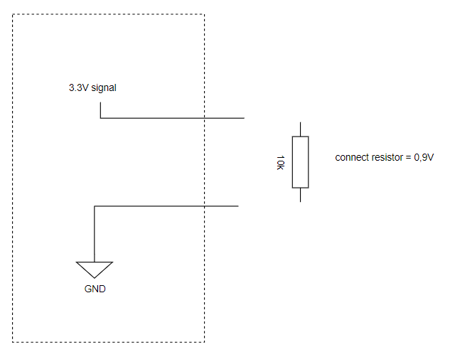
I'm not sure how to describe it precisely, but I managed to establish a signal that operates between 3.3V and 0.9V by employing a 10k resistor. When I touch the points corresponding to 3.3V and GND, there's a noticeable effect. However, I'm uncertain about the functionality of the rest of the circuit.
Do I require a transistor to control this signal from Arduino, or can I directly use Arduino to manipulate the signal to go high/low, possibly employing a voltage divider as an example?
How did you achieve that with one resistor that is connected to nothing???
What is your exact goal? What would you like to achieve in the end?
What noticable effect?
Sorry, your post is far from clear...
i was using arduino uno, i managed using to control pull-up switch using a transistor, controlling base using the arduino. I thought that the perhaps i could use the build in software internal_pullup to make the same thing in code but nope, thats was too complicated so went with keep it simple!
You almost have it, that is part of the internal hardware, the software can only enable/disable it. I fnd they are in the 30K range sometimes more, making the weak for switches that have any length of wire on them. Here is an example for pin 2: pinMode(2, INPUT_PULLUP);. I suggest you skim the Arduino Cookbook in your spare time, it will explain all of this and many other things.
Not all pins are the same but most of them are digital in nature. That on the UNO says they should be at 5V or 0V. If they are inputs you need to externally supply that signal. If they are outputs the Arduino will supply the current. This is controlled with the pinMode statement: See this link for a much better explanation. pinMode() - Arduino Reference The outputs are limited to a very small amount of current, best kept under 10 mA. Inputs should not exceed the 5V of the Arduino or go negative below ground. There are analog inputs, which will divide its reference voltage (usually VCC [5V] on the UNO) by 0-1023. A zero would indicate zero volts, 1023 would indicate 5V (the reference voltage). It is not exact as there is steps involved.
You can use a voltage divider on either input or output, On input you would use it to divide down a higher voltage to a range the UNO can use. On the output it would divide the voltage down to a lower voltage something else needs. NEVER use the UNO to power anything from its port pins, they are for signals only. Hopefully this helps.