Hello friends,
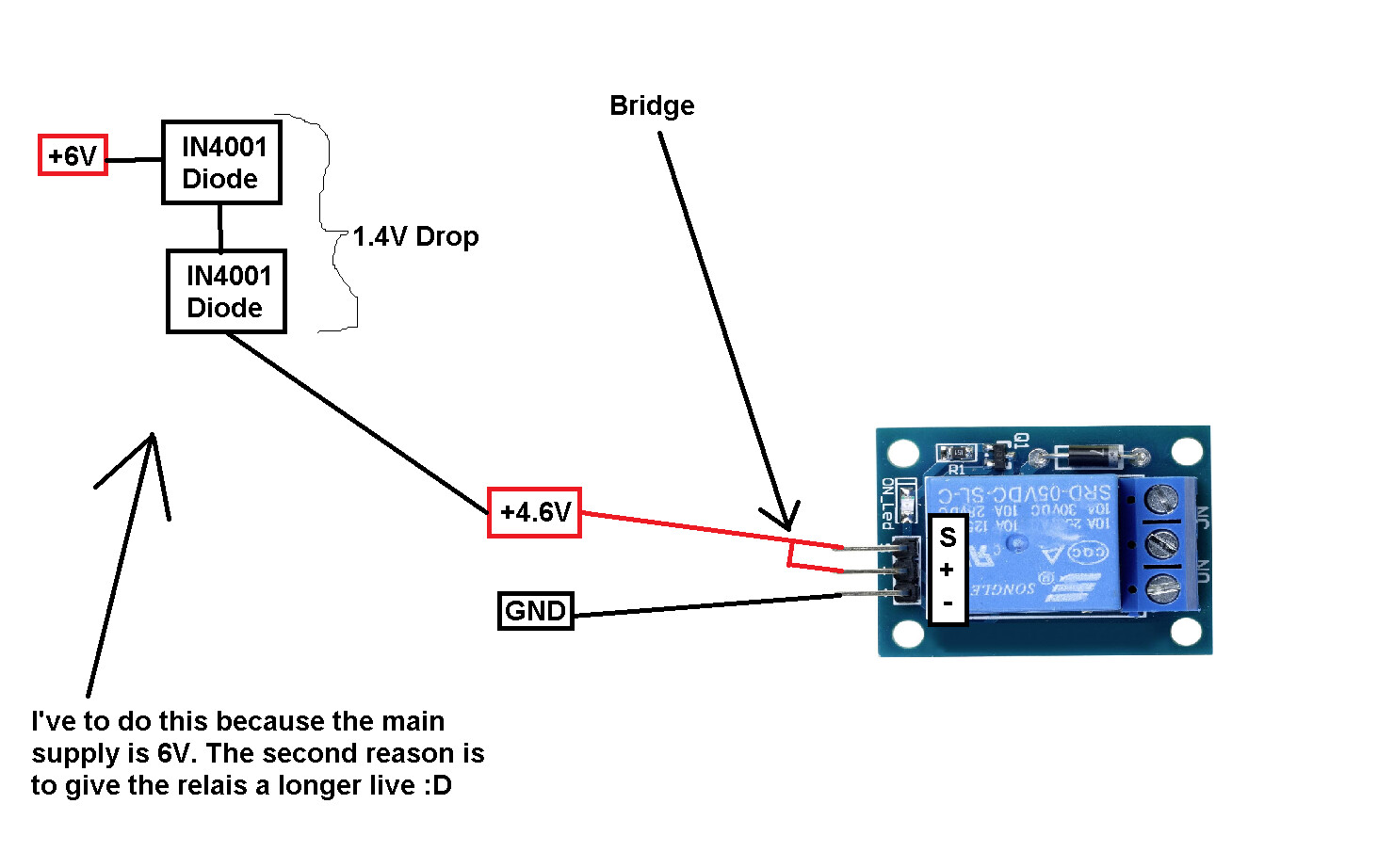
I've a question, can I use these relais (see photo 1) with a bridge on it ?
What happens when you try the modifications.
1 diode might be good enough.
When S is connected to GND (-) what happens ?
If I do it like you see, than the relais activates. I know that. But would there be a long term harm to the relais ?
I would never connect the 'S' to the 'GND'. This would be the death sentence for the relais ![]()
Don't be such a doom monger - the relay will just go to its unoperated state.
There is a datasheet (in German) for that relay module here. The example sketch controls the relay using the 'S' pin connected to an Arduino digital output.
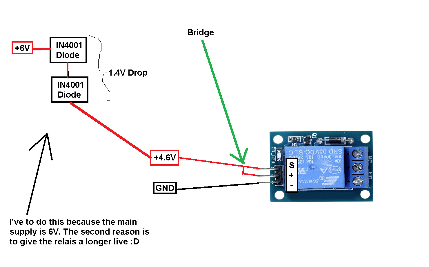
Again: I've never said that I'm gonna connect the S Pin to the GND. Maybe you all understood it wrongly because I used the wrong color. My question is only regarding to the bridge. See again with the correct wiring color (Grüße aus DE).
You can connect the S pin 3 different ways.
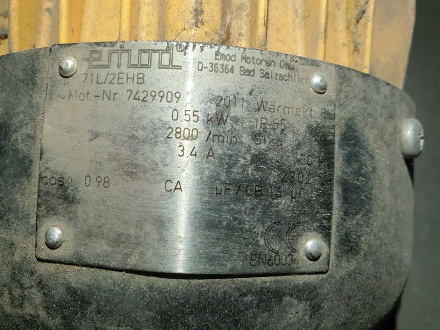
But I've had an inctident with this relais. I allways used 5V to power them up. Than, one day, the relais stucked in an active state. My 230V water pump was running, and running. I have searched for error, but could not find. Than, I hit the relais with a screw driver, and than it stopped. So the error was maybe that the 5V is not good for these cheap chinese relais ? Since than, I only use 3.3V to power them up.
More than likely your relay contacts welded together which cause the load to continue to be powered.
Tapping the relay case opens the welded contacts.
These relays are poor quality and the contacts usually fail.
Okay, but does it make sense if I would use 3.3V in the future the make them longer live ?
Or was the "Current of the Water Pump" the problem ?
I would consider using a solid state relay, they have no contacts and will do zero crossing. This is similar to the ones I use:
 You also will no longer need the diodes.
okay thanks.
Okay, this is a good idea too. Thanks.
What are the specifications of your pump ?
This fact has absolutely nothing to do with contacts weld
My question is only… doesn't that mean the relay will be permanently doing one thing, and no longer be a switchable element in your design?
Wire is cheaper, in,escs that's supposed to be a power failure indicator relay, yeh that's the ticket.
a7
What's purpose of that bridge? It make the relay always activated as soon as it is turned on
It should not be switchable. I want to power it up, and give a signal to S at the same time. So is it okay to bridge them up ? I only wanna have one state.