in a first realisation using 6 relais for switching model-railway-tracks
the relais switched in a unplanned manner what is strongly forbidden in my situation
the relais-electronic is feed at 5V by the same source as ardiuno.
didnt find any useful documentation for using relay with arduinos..
questions
the trigger-input of relais was directly connected to a digital pin of arduino nano.
is that correct ?
does the trigger input of relais need pullup-resistors connected to VCC , maybe 4k7 ?
are condensators needed from trigger-pin to ground ?
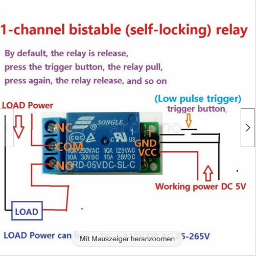
The above is the part number for the actual relay component on the board rather than the module in the image.
Are you sure that what you have is a latching relay module? The picture you provided looks to be that of a simple on/off relay module. If it were latching, then I would have expected additional components to be visible. Perhaps they are mounted on the underside of the board.
I would be suspicious of that image as the wording says that the relay can handle up to 265VAC but the manufacturers printing on the relay itself says only 250VAC.
void setup() {
  Serial.begin(9600);
  // initialize digital pin LED_BUILTIN as an output.
  pinMode(led_red, OUTPUT);
  pinMode(led_yellow, OUTPUT);
  pinMode(led_green, OUTPUT);
  pinMode(pin_digi_bistab_rel, OUTPUT);

  digitalWrite(led_red, LOW);   // turn the LED on (HIGH is the voltage level)
  digitalWrite(led_green, LOW);    // turn the LED off by making the voltage LOW
  digitalWrite(led_yellow, LOW);
  digitalWrite(pin_digi_bistab_rel, HIGH);  //- FlipFlop of Relais needs negative Impulses !
}

// the loop function runs over and over again forever
void loop() {
  digitalWrite(led_red, HIGH);   // turn the LED on (HIGH is the voltage level)
  delay(TIME_TEST_LOOP);                       // wait for a second
  digitalWrite(led_red, LOW);    // turn the LED off by making the voltage LOW
  delay(TIME_TEST_LOOP);                       // wait for a second
  digitalWrite(led_yellow, HIGH);    // turn the LED off by making the voltage LOW
  delay(TIME_TEST_LOOP);
  digitalWrite(led_yellow, LOW);    // turn the LED off by making the voltage LOW
  delay(TIME_TEST_LOOP);
  digitalWrite(led_green, HIGH);    // turn the LED off by making the voltage LOW
  delay(TIME_TEST_LOOP);
  digitalWrite(led_green, LOW);    // turn the LED off by making the voltage LOW

  Serial.println("..new pulse");
  send_pulse();
}

void send_pulse()
{
  digitalWrite(pin_digi_bistab_rel, LOW);
  delay(30);
  digitalWrite(pin_digi_bistab_rel, HIGH);
  //delay(30);
  //digitalWrite(pin_digi_bistab_rel, LOW);
}
I found another view of that relay module and there's a small 4-pin SIL device just to the right of the relay body. I guess that takes care of the latching process.
I believe you are in for a lot of long nights if you consider that a latching relay. Per the data sheet is is a pseudo standard form C relay with a 5VDC coil, 0.36W. The latching function can be implemented with additional circurity on the board but when the power goes away the the contacts will revert to the normal position. The NC contact will close and the NO will open.
Using software, a couple lines of code can turn regular relays into latching devices.
You can even save latched states thru a power off condition by writing a relay’s state to EEPROM in the Arduino.
Example
There are a lot of 8 channel relay modules available that look similar to this.