I'm planning on building an automation system. There's two sensors that should connect to the Arduino Nano v3. The A4 port will connect to ports SDA from each sensor. I guess the standard way of doing this is by means of a stripboard, but I find it an exaggeration to employ one just for this small project. Also, I want to make a permanent installation. Question: Can I connect multiple wires to the same A4 port? if so, how to proceed? I'm considering using a standard busbar for this. What do you guys think?
Welcome to the forum
You can certainly connect more than one device to the I2C bus pins. That is how a bus system works
As to how you make the physical connection, if it is a permanent installation then using perf board is not overkill. Another possibility would be to use a carrier board like this one
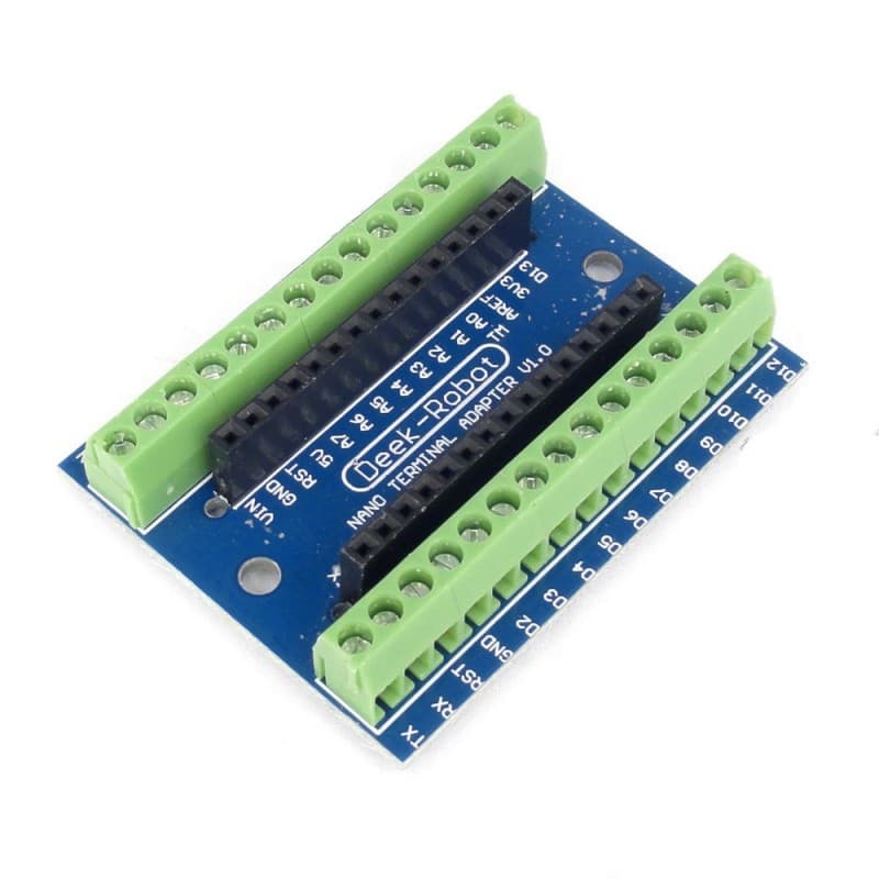
The Nano plugs into it and connections to the Nano use screw terminals. This would allow more than one wire to be used in a single terminal
You do need to make sure that the devices have different I2C addresses.


Not much if what you are building is a permanent installation
A 150A busbar is overkill
Solder your Nano to stripboard. (Don't forget to break the strips under the Nano.) Solder as many pairs of PCB header pins as you need to the strips from A4/A5.
It might be convenient to use 2 strips adjacent to the A4/A5 strips for ground and 5V. If you do that, don't forget to break those strips so they don't connect to A3,A6 or A7, and leave at least one free hole connected to those pins in case you need to use them later.
You can then use 4x female header sockets to connect your remote i2c devices. But don't forget that i2c isn't meant for long distances. You might get 1~2m if lucky.
If you are going to use stripboard for the permanent installation then why bother to use PCB headers and loose plugs or sockets intended to be used for prototyping ?
Sometimes it can be convenient for construction & installation and ease of replacement.
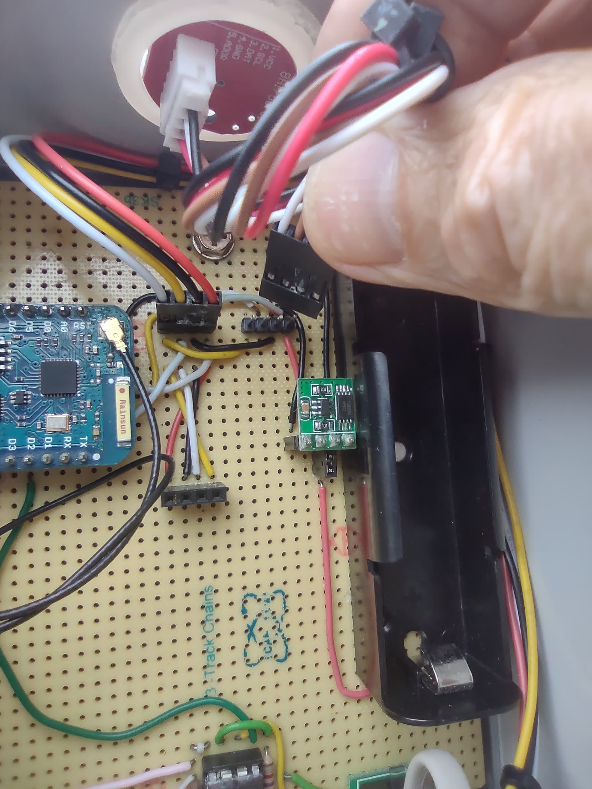
For example in my weather station, I used these sensors:
SHT30 Temp/Humidity sensor:
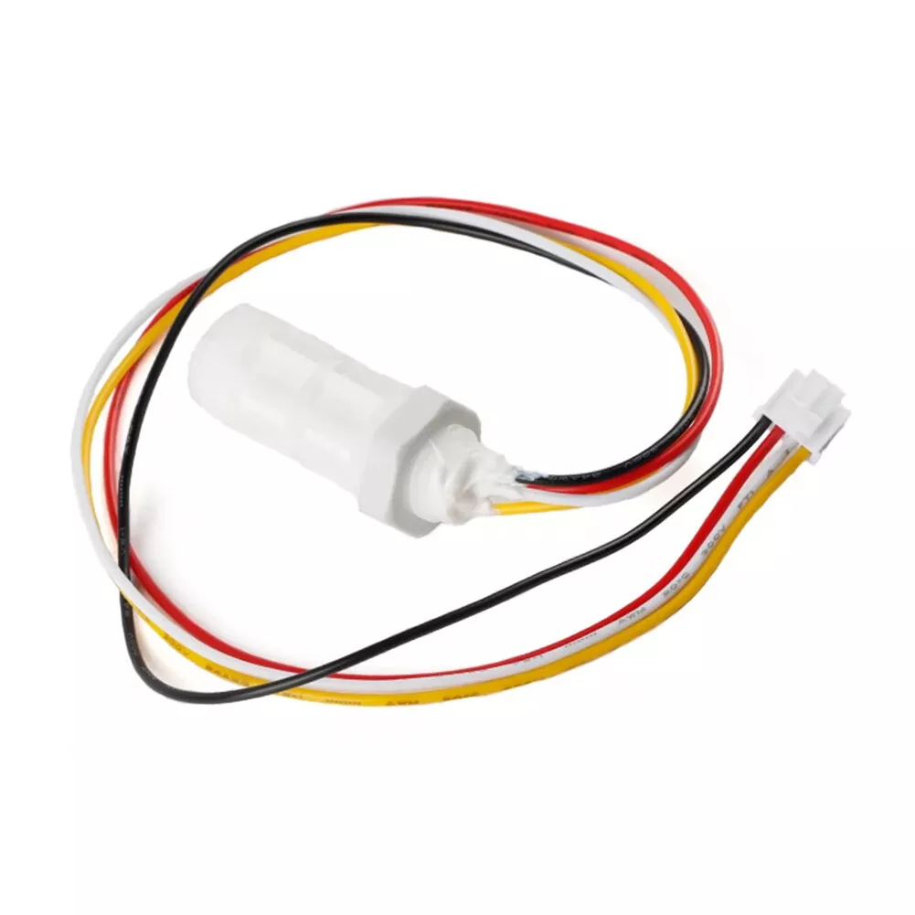
BH1750 light sensor:
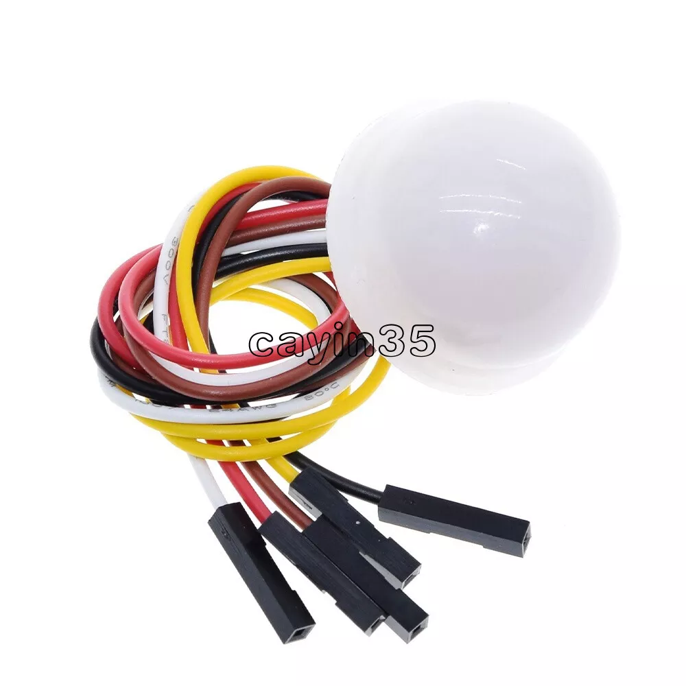
With both sensors, I replaced the provided connectors with 4-way female crimp connectors. The sensors are mounted on the outside of the case.
wow cool. What you mean by "10 seconds"?
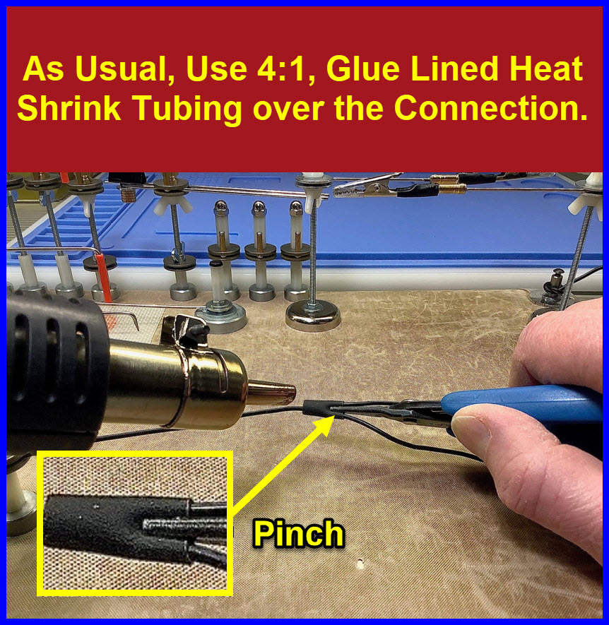
Indeed you would, but
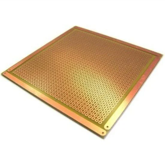
They are perfboards, not stripboards, there are no strips. And I can't believe stripboard is not available, in your country or any country. It's not exactly cutting edge technology! ![]()
Maybe search for "Veroboard".
That's the time needed to make it.
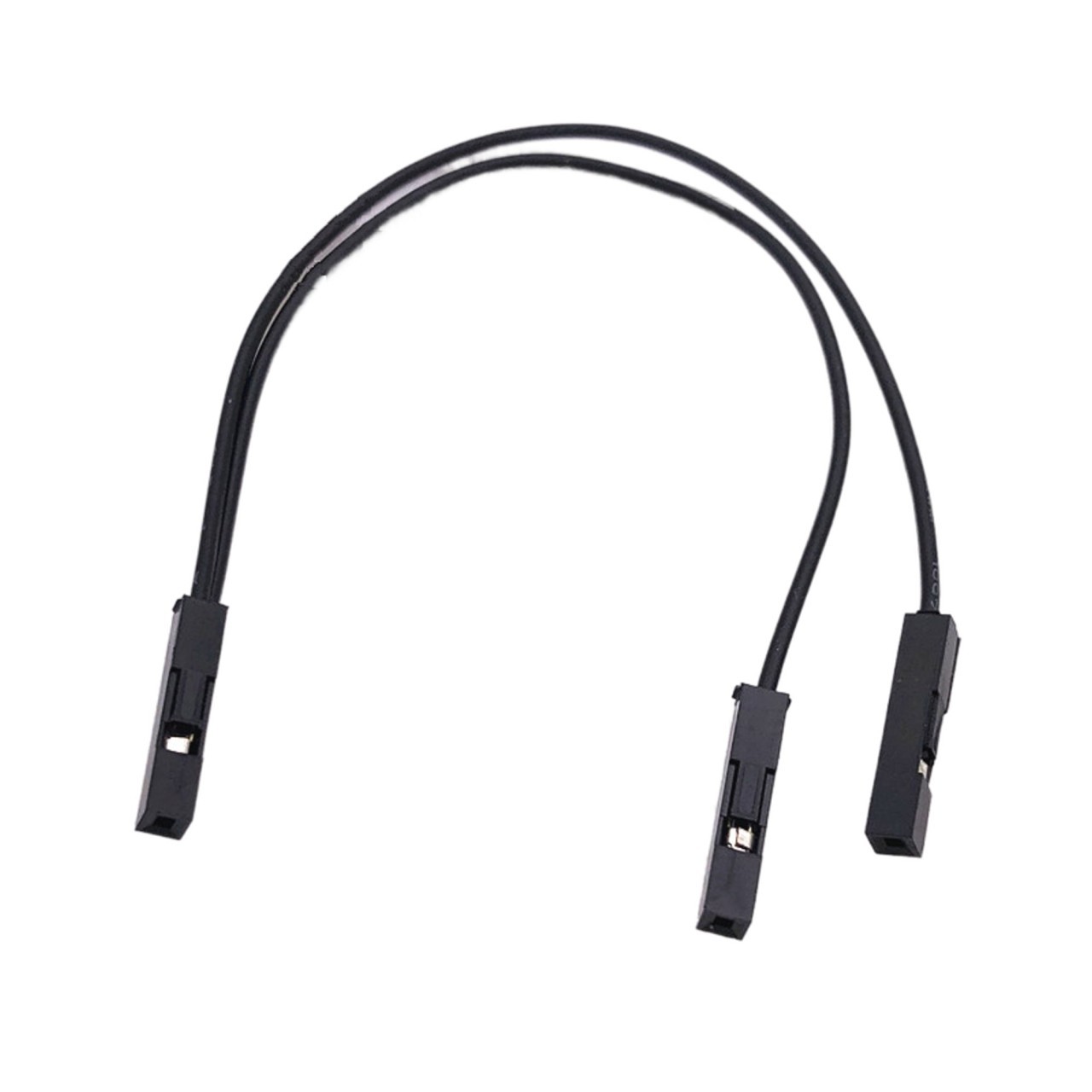
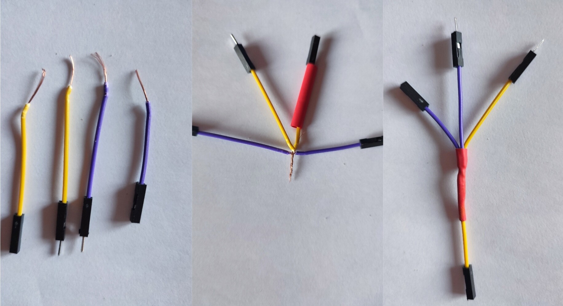
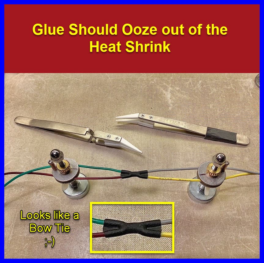
Cut in half two jumper wires. twist them together and apply heat shrink for protection.
But what LarryD posted is more robust and elegant of course.
maybe because I'm searching in English, I don't even know what they are called in my native language. ![]()
- some context helps
Which is?
In other words what is your native language?
Perfboard or stripboard are both prototyping boards. You just have to use some ingenuity to adapt them to your project.
Personally, I don't use perfboard much and mostly use stripboard. Both have advantages and disadvantages. One has isolated pads, so you make the connections, the other has the connections and you do the isolating by cutting the strips.
If you have a lot of SIL, DIL packages like CMOS DIP devices, then stripboard is easier.
I buy a large sheet of stripboard and chop it up into smaller, say 50-mm x 50-mm pieces. Cutting is by score and snap.
Perf or strip, look out for gold flash or tinned coatings to make soldering easier.
Some boards are designed for rack systems, Eurocards, 100-mm x 160-mm with headers to slot into a backplane.
For more finished projects, I use FR4 (fibreglass) boards with PTH (Plated Through Holes), which are sturdier, hold components better and allow some double sided work. Connections can be by deliberate solder bridging.