Trying to figure out if level shifters can link the 5v levels of HX711 SCK/DT I/Os to the 3.3v levels of low power MCU digital pins when the HX711 VCC input is driven at 5v.
Generally accepted practices appear to be either to switch to a sparkfun board which separates VCC from VDD or to hack the module as per the sparkfun design pattern.
Is there any specific reason why the SCK/DT lines can't just be shifted low to connect with 3.3v pins directly? I have searched all over google but can't find any explanations for why this should not be done.
Tried Jremington's board suggestion a few times but the HX711_ADC library I used throws up this error.
"Timeout, check MCU>HX711 wiring and pin designations"
I had both data and clock lines on the level shifter though.
Edit: Everything works fine when the HX711 module is powered with 3.3v. Error only shows up when i try to power it with 5v and then shift the signal lines lower. [End Edit]
Haven't attempted using voltage dividers on the data line.
Going by your inputs, it seems there should be no reason why changing levels on SCK/DT shouldn't work. However, most of the stuff i read on this forum went straight to one of the two options i mentioned earlier.
@Leo: can the pin connected to SCK feed the HX711 board with 3.3v logic directly?
The data pin of the HX711 is an output, and the clock pin is an input.
That makes me think you only need to level shift the data pin.
Not sure if the HX711 accepts a 3.3volt-logic clock signal.
Why don't you try changing that HX711 board for dual supply.
Leo..
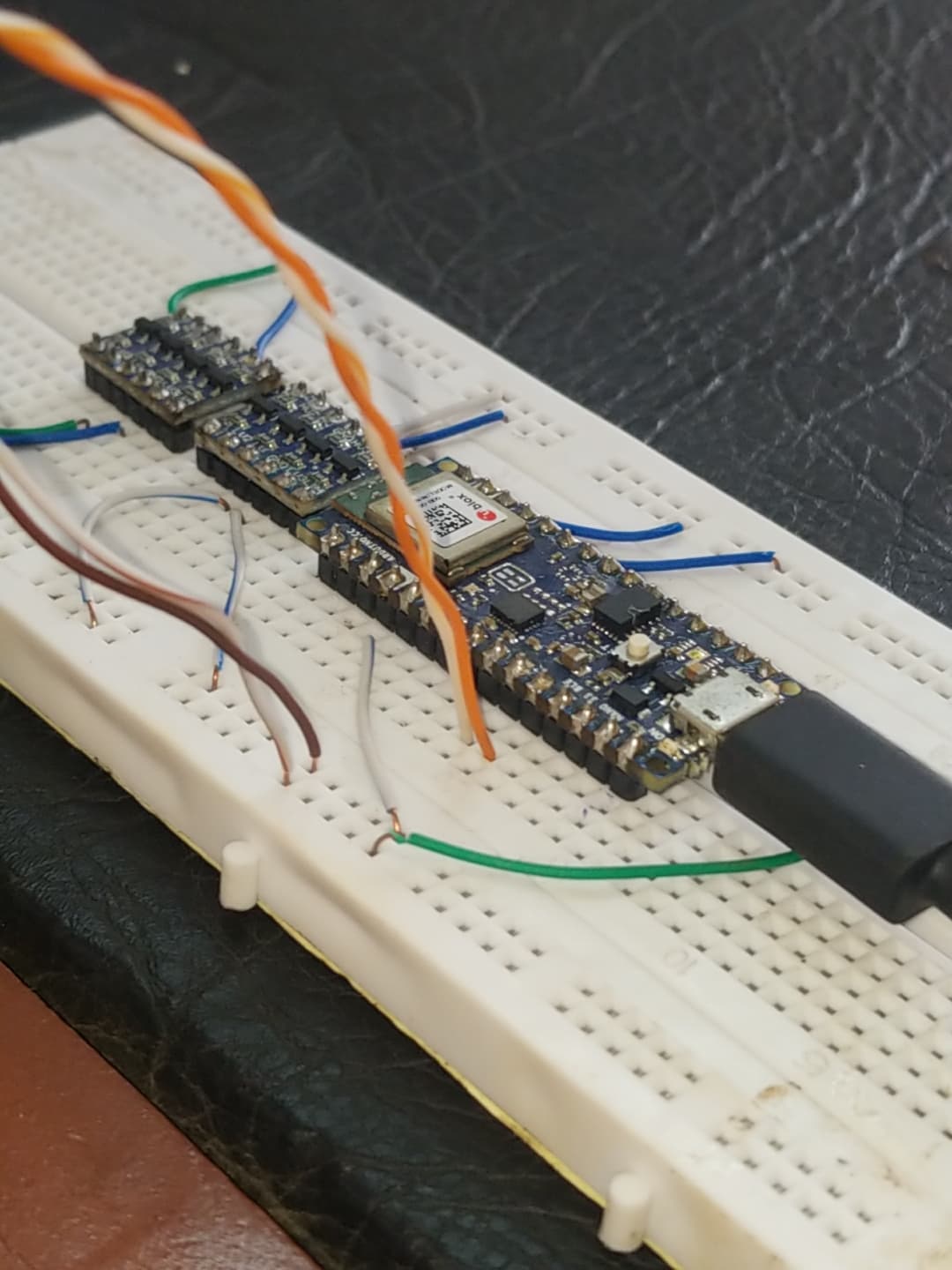
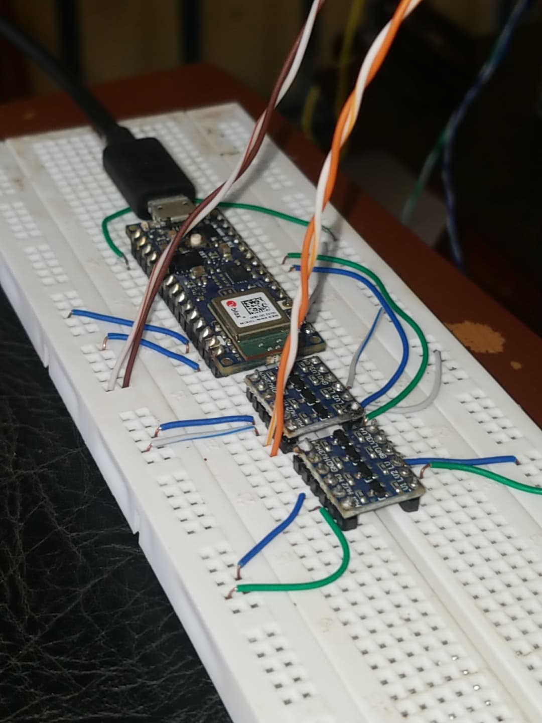
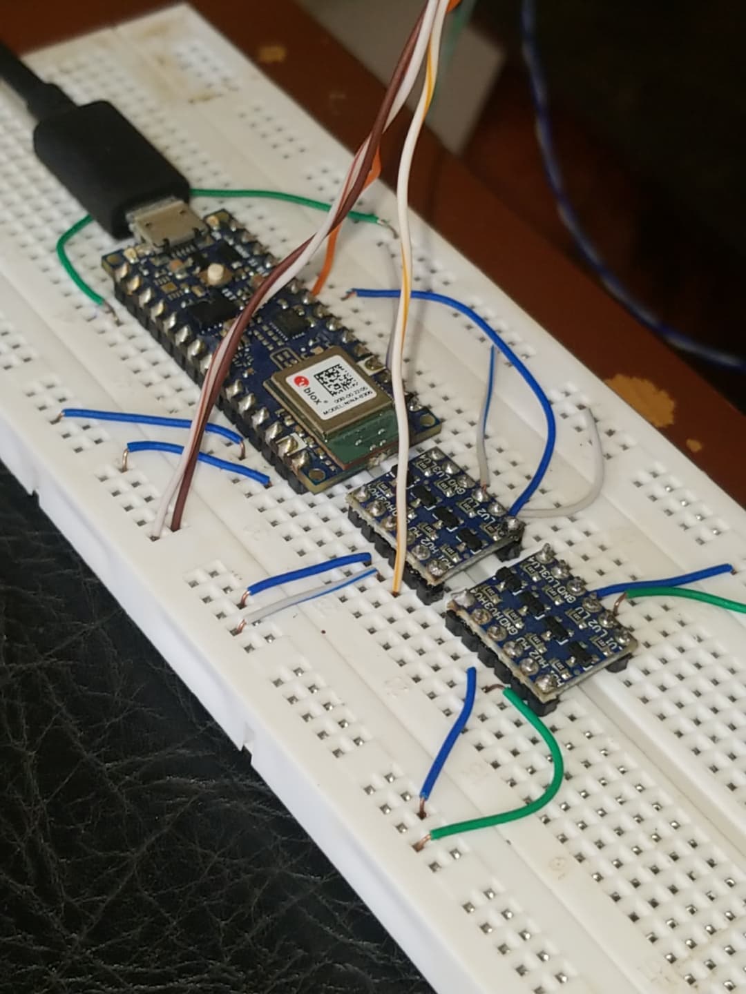
Howdy folks. Got round to testing with only DT going through the logic converter. Worked splendidly on the first try. Big thanks to Leo and Jremington.
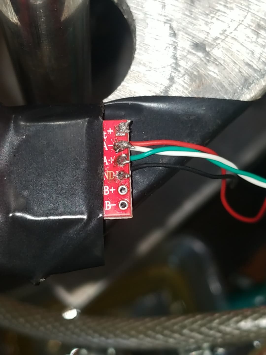
Added a few pics of my setup. My soldering skills aren't spectacular but nothing seems to shake if I pull at the wires lightly.
It seems strange that running SCK through the shifter throws up the error. One would expect that to be the standard way of wiring the module to the nano (33 BLE). Any thoughts on what might be happening there?
Those level shifters are designed for I2C, which is passive pull up and active pull down.
To level shift a digital push/pull signal, you should use digital ports, like this one.
Can you still try the 1k:2k (2k2) voltage divider I mentioned, no level shift boards.
Leo..
Tried the 1k:2k voltage divider and it worked fine (no suprises there).
I suppose it's more efficient compared to using level shifters cos there are fewer components and smaller resistances involved, hence less power draw. Thanks for the tip Leo.
Basically, HX711 SCK port is not compatible with level shifter conversion techniques. Use a digital port instead. However, SCK port accepts 3.3v straight from 3.3v MCU so digital port is not strictly necessary.
Thanks everybody.
As a side note, anyone looking to use the HX711_ADC library for a nano 33 BLE will have to:
change INPUT to INPUT_PULLUP in the .cpp file of the library
modify appropriately or comment out all the sections of code related to EEPROM.