Hey, I want to use the OLED Display of my heltec esp32 v3 wifi kit. I want to use the u8g2 library to write on the display. The code uploads without any errors but the display wont turn on, its just black. Can anybody help me please ?
Here is the code:
/*
  Sketch generated by the Arduino IoT Cloud Thing "Untitled"
  https://create.arduino.cc/cloud/things/f1938a94-5d7d-4030-8200-967dcd5ef81c

  Arduino IoT Cloud Variables description

  The following variables are automatically generated and updated when changes are made to the Thing

  CloudLight lED;
  int poti;

  Variables which are marked as READ/WRITE in the Cloud Thing will also have functions
  which are called when their values are changed from the Dashboard.
  These functions are generated with the Thing and added at the end of this sketch.
*/

#include "thingProperties.h"
#include "U8g2lib.h"

#define OLED_CLOCK 15
#define OLED_DATA 4
#define OLED_RESET 16

U8G2_SSD1306_128X64_NONAME_F_SW_I2C g_OLED(U8G2_R2, OLED_CLOCK, OLED_DATA, OLED_RESET);
int g_lineHeight = 0;

const int PotPin = 1;

void setup() {
  // for OLED Screen
  g_OLED.begin();
  g_OLED.clear();
  g_OLED.setFont(u8g2_font_profont15_tf);

  g_lineHeight = g_OLED.getFontAscent() - g_OLED.getFontDescent();

  g_OLED.setCursor(0, g_lineHeight * 2);
  g_OLED.printf("This is a Test");
  g_OLED.sendBuffer();

  // Initialize serial and wait for port to open:
  Serial.begin(9600);
  pinMode(19,OUTPUT);
  pinMode(PotPin,INPUT);


  // This delay gives the chance to wait for a Serial Monitor without blocking if none is found
  delay(1500);


  // Defined in thingProperties.h
  initProperties();

  // Connect to Arduino IoT Cloud
  ArduinoCloud.begin(ArduinoIoTPreferredConnection);

  /*
     The following function allows you to obtain more information
     related to the state of network and IoT Cloud connection and errors
     the higher number the more granular information you’ll get.
     The default is 0 (only errors).
     Maximum is 4
 */
  setDebugMessageLevel(2);
  ArduinoCloud.printDebugInfo();
}

void loop() {
  ArduinoCloud.update();
  // Your code here
  poti = analogRead(PotPin);


}


/*
  Since LED is READ_WRITE variable, onLEDChange() is
  executed every time a new value is received from IoT Cloud.
*/
void onLEDChange()  {
  if(lED==1){
    digitalWrite(19,HIGH);
  }
  else{
    digitalWrite(19,LOW);
  }
  // Add your code here to act upon LED change
}

/*
  Since Poti is READ_WRITE variable, onPotiChange() is
  executed every time a new value is received from IoT Cloud.
*/
void onPotiChange()  {

  if(poti>=0 && poti<=1000){
    Serial.print("Potivalue:");
    Serial.print(poti);
    delay(1000);
  }
}
I would start with the example from the vendor/manufacturer and make it run.
When that sketch is running - post it also.
It makes it far easier to figure out the right pins and afterwards switch to another library.
I tried it with the Heltec Library of the manufacturer and it worked in the arduino IDE, but for this library you need inlcude a URL in the properties, which wont work in the web version of arduino i want to use.
So i switched to the u8g2
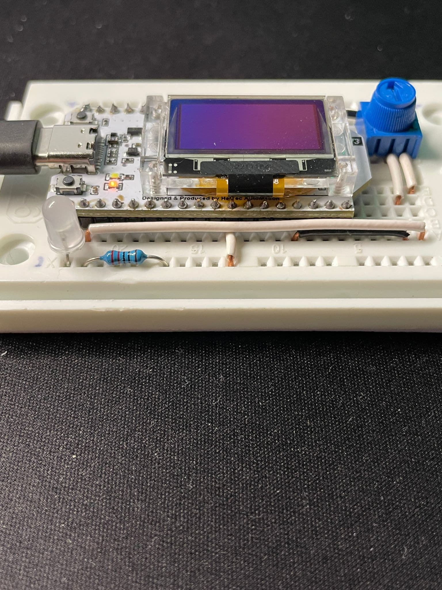
Hey guys, so thanks for helping, I am still a beginner an appreciate your help. There are two pictures where you can see the wiring. There is also a pinout of my esp32
So I changed the code a little:
I removed the #defines and wrote the pins directly in the code
I added the g_OLED.display
I changed the poti pin to 4 instead of 1
It wont work anyway, please send help....
/*
  Sketch generated by the Arduino IoT Cloud Thing "Untitled"
  https://create.arduino.cc/cloud/things/f1938a94-5d7d-4030-8200-967dcd5ef81c

  Arduino IoT Cloud Variables description

  The following variables are automatically generated and updated when changes are made to the Thing

  CloudLight lED;
  int poti;

  Variables which are marked as READ/WRITE in the Cloud Thing will also have functions
  which are called when their values are changed from the Dashboard.
  These functions are generated with the Thing and added at the end of this sketch.
*/

#include "thingProperties.h"
#include "U8g2lib.h"
#include "Wire.h"

U8G2_SSD1306_128X64_NONAME_F_SW_I2C g_OLED(U8G2_R2, 21, 22, 15);
int g_lineHeight = 0;

const int PotPin = 4;

void setup() {
  // for OLED Screen
  Wire.begin();
  g_OLED.begin();
  g_OLED.clear();
  g_OLED.setFont(u8g2_font_profont15_tf);

  g_lineHeight = g_OLED.getFontAscent() - g_OLED.getFontDescent();

  g_OLED.setCursor(0, g_lineHeight * 2);
  g_OLED.printf("This is a Test");
  g_OLED.sendBuffer();
  g_OLED.display();

  // Initialize serial and wait for port to open:
  Serial.begin(9600);
  pinMode(19,OUTPUT);
  pinMode(PotPin,INPUT);


  // This delay gives the chance to wait for a Serial Monitor without blocking if none is found
  delay(1500);


  // Defined in thingProperties.h
  initProperties();

  // Connect to Arduino IoT Cloud
  ArduinoCloud.begin(ArduinoIoTPreferredConnection);

  /*
     The following function allows you to obtain more information
     related to the state of network and IoT Cloud connection and errors
     the higher number the more granular information you’ll get.
     The default is 0 (only errors).
     Maximum is 4
 */
  setDebugMessageLevel(2);
  ArduinoCloud.printDebugInfo();
}

void loop() {
  ArduinoCloud.update();
  // Your code here
  poti = analogRead(PotPin);

}


/*
  Since LED is READ_WRITE variable, onLEDChange() is
  executed every time a new value is received from IoT Cloud.
*/
void onLEDChange()  {
  if(lED==1){
    digitalWrite(19,HIGH);
  }
  else{
    digitalWrite(19,LOW);
  }
  // Add your code here to act upon LED change
}

/*
  Since Poti is READ_WRITE variable, onPotiChange() is
  executed every time a new value is received from IoT Cloud.
*/
void onPotiChange()  {

  if(poti>=0 && poti<=1000){
    Serial.print("Potivalue:");
    Serial.print(poti);
    delay(1000);
  }
}
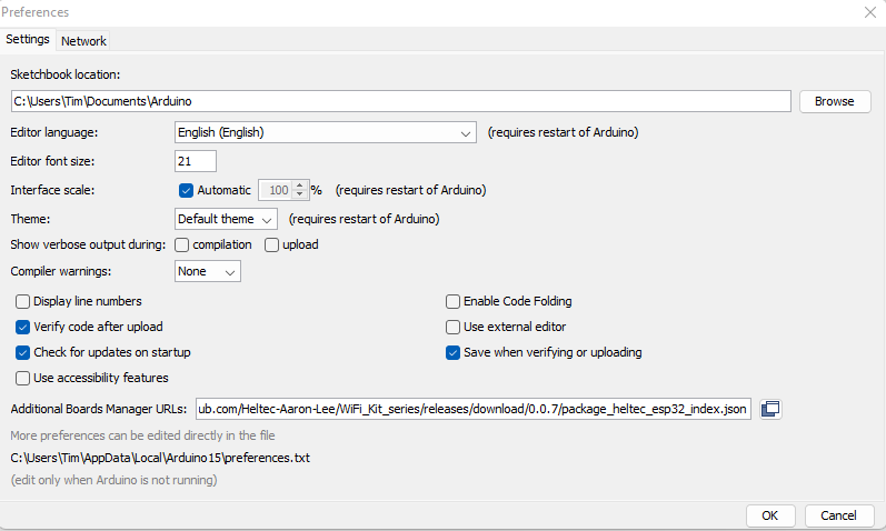
Thanks for your answer, so arccording to several YT videos you need to include this URL in the Software (see picture below). Without it it wont work, but in the Online version of arduino there is no option to do that, but i need the online version because i want to control the led via IOT Cloud.
The Arduino IoT Cloud is for Arduino boards with Wifi, and no "json" URL for additional boards can be added. But it also works for the ESP8266 and ESP32.
Do you have a ESP32-S3 ? That is not a ESP32, but it is part of the ESP32 build environment.
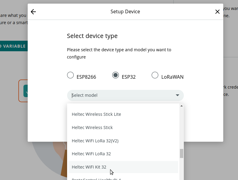
In the Arduino IoT Cloud, I can select non-Arduino boards and there is your board:
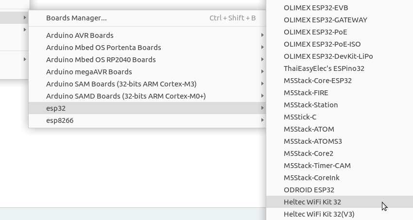
I suggest to remove the special "json" URL for additional boards in the Arduino IDE from Heltec. It is probably an older version of the ESP32 build environment. Use the common ESP32 "json" URL for the newest version (https://raw.githubusercontent.com/espressif/arduino-esp32/gh-pages/package_esp32_index.json) and your board is there are well:
Thanks, but i already tried it, when i select the heltec wifi kit 32 it wont work, it says wrong chip (because i have the v3 version of the board). So i have to use the esp32v3 model and then it works.
In the Arduino IDE i change the URL and it works, thanks but i want to make it work in the online arduino ide, and i want to make the heltec library work or use the u8g2 lib for the display on my board
Here is the error code when uploading with the heltec wifi kit 32 selected
So the first version of the Heltext Wifi Kit 32 uses a ESP32 and they changed to ESP32-S3 for the "V3" version. Then you are out of luck for the Cloud IoT
I assume that it will be added someday.
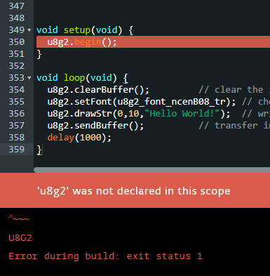
Hey, so i tried the u8g2 hello world example you sent me.
It doesnt work, here is the error code:
So i tried the example of the ssd1306 lib in the Arduino IDE, and i can write on the display, but when i put the same code in the online editor it wont work because it doesnt recocnize the lib.
Here is the code:
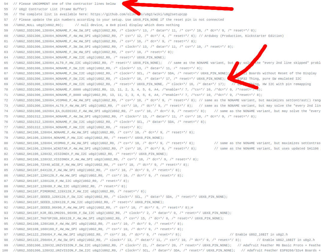
In case you don't know the u8g2 library, I wrote: "Show the sketch that you used for the test".
Because you have to select the bus, the mode and the pins.
I'm confused.
The Arduino IDE does not have examples of the SSD1306 by itself, those examples are from a library that you have installed.
I don't use the online editor and I don't know which library you use in the Arduino IDE.
Do you have it working with pin 21 and 22 for SDA and SCL in the Arduino IDE ?
Is that enough to work on your project for now ?
Is it possible to buy a previous version of the Heltec board (with the ESP32) ? That is a weird solution, but sometimes you have go with what is possible.