I have a need for an arduino board with castellated holes. (my own design also carries a max485 IC) I have a PCB design ready to order with smd assembly but it would mean a bulk order which sets me back like atleast €450,-
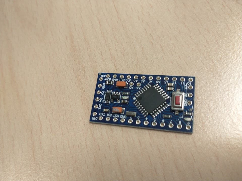
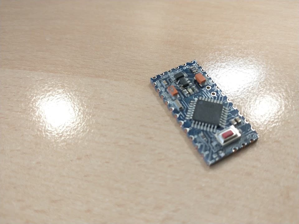
I am not yet ready to start with the mass production. As an intermediate solution I want to try out an arduino pro-mini. I like that it is flat on the bottom side, it is 12mm shorter than a nano every and there is a 3V3 variant (which I need)
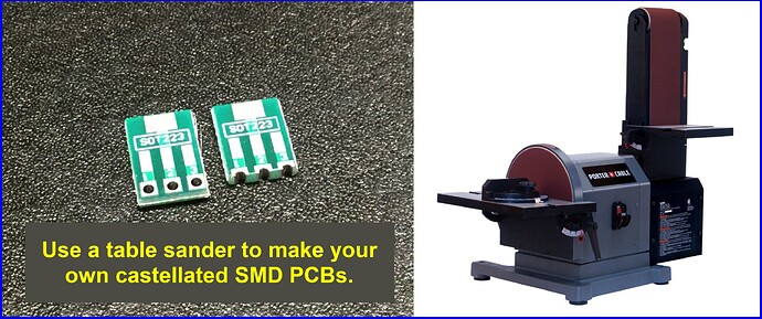
My brainfart: can you sand off the edges to make it's holes castelled holes? without breaking something that is I do not have one lying around at this moment to test. Looking at the photos there seem not to be traces between the outer holes and the edges. At work we have a big sanding machines which should make the job easy,
Because I can solder such a board flat to a larger carrier board. The carrier board is a control panel which is also a front end. I don't want through hole components sticking through.
Because only one control panel is ever needed, SMT assembly for the entire thing is out of the question. + It would take me too much labour to keep redesigning the exact same uController circuit for every panel.
This one is mine, but I made two more for others and I expect to sell more of these. The ones I made so far are connected to a separated controller board via dupont or flatcables. You can see a 19 pin connector on top. This I will keep as an option, but I prefer to have the controller unit on the control panel.
This is 20 minutes intensive labour here from designing to soldering.
My own controller has an onboard max485 IC and I2C EEPROM.
Because I am most likely going to lack IO pins for certain control panels I may need more than one unit per LED. The second or third units, could also be pro mini's. They will act as IO extender They are slightly smaller than my design. I would prefer MCP23017 but they are more expensive than a pro mini. Shiftregisters do not suffice because they don't have tri-state capabilities
The reason I need 3V3 is that I can control 2 leds with 1 pin with 3 different states. The leds are connected in series and have a 1,8V voltage drop. So I can either turn 1 of 2 leds on, or turn them both off by making the pin an input. I tried with 5V, but despite 2 leds and 2 5K resistors in series the leds were still to bright.
The controller can be programmed and configured via the ICSP header and a 2x3 pogopin clamp. Underneath this header there is a keepout zone planned.
And lastly I have a video of a working protoype. (Comments're in Dutch though). The panels can record and replay actions. This consumes a lot of EEPROM. Also the new source code will be able to store routes in eeprom and calculate routes on the fly. This is a must have for large control panels.
Can you design plated through holes on the board edge, then have your board house machine V-grooves through the center of the holes? Then you can break off the tab and have what you want. For production, make many boards in a panel so the V-grooves are between adjacent boards. Break by hand or use a segregator to cut the v-groove.
I am aware. I will make a keepout zone. Were I to lack 1 or 2 whole IO pins, I will happily solder a wire to A4 and A5.
I also miss A6 and A7. I often use A7 in combination with a resistor divider in order to set a peripheral address.
@Larry I have lots of buck converter backpacks in many designs. I still cannot beat the prices to add my own buck converter design for the small amounts. And for those four solder pads, the labour is not that much.
I happen to find a stray pro-mini in my programmables inventory. I hid it in my pocket so I will magically find it tomorrow @ work. That always works the other way around when I suddenly find a CF card in my pocket.
Tnx for the advices. I'll let you know if I break any of the tiny little holes... or not.
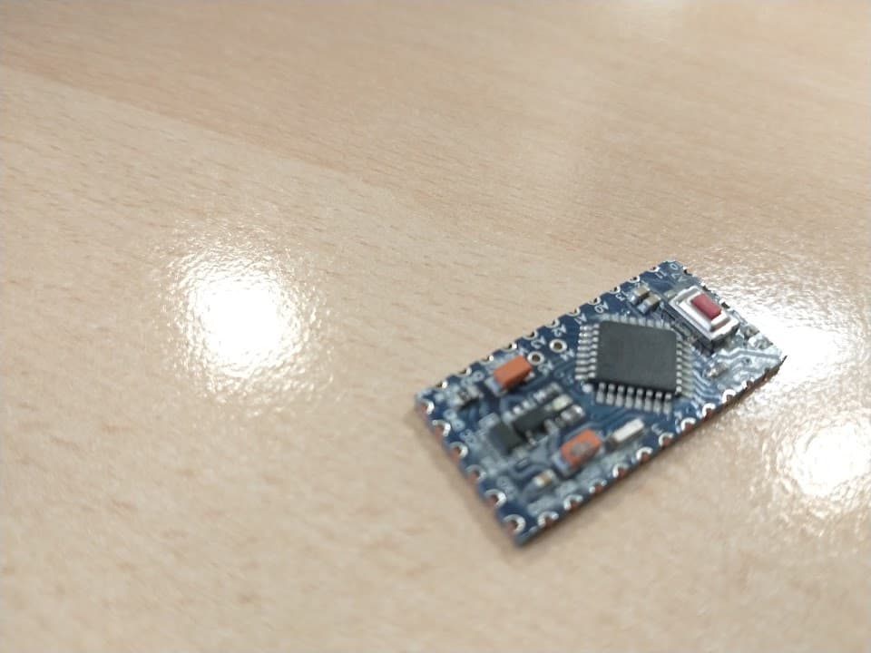
I almost lost pins 6 and 10 Sanding does work though
The copper is now exposed. If I solder all the pads (and the remains of pads 6 & 10) completely so that no copper is exposed will it eventually still oxidate and 'go bad' or can I expect alteast 10 years of loyal service?
Another question. The bottom side shows me 'the simple', '5v' and 3 different clock frequencies. Judging on the 5V I think this is a 5V variant. Those clock frequencies (8, 16 and 20MHz). Can I select any of them in the IDE? The tasks only exists out of reading some switches and control some LED. I do want to use SW serial libary for B2B communication. I'd prefer 8MHz in order to reduce current consumption.
Nvm found the fuse settings in the IDE
Hi,
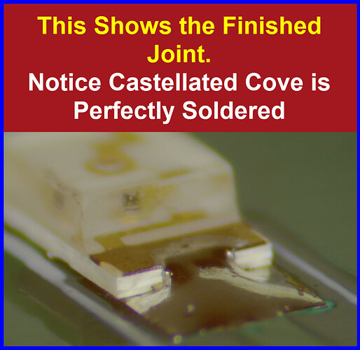
Make sure when you solder, that the solder runs the full depth of the opened plated through hole, to make sure you cover any cracks in the plated surface.
I have another brainfart. To use this pro mini I must make a footprint with SMD pads to solder it on and order some PCBs.
What if.... I did not sand this board. Could you lie the pro-mini over that footprint with the SMD pads so that the holes of the pro-mini are precisely over the pads. Than you add enough solder to the top of the holes so the solder goes through the hole and actually attach to the SMD pad underneath the hole??
I remember from soldering those double sides proto PCB's some 15 years ago that solder flows into those plated hole easily. I found it annoying at the time for some reason.
I imagine it would be somewhat tricky to outline. But than again we have silktexts nowadays
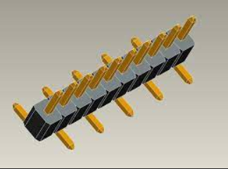
I also keep those single row SMT headers as an open option.
I have a piece of 16mm MDF, half the size of a sheet of sandpaper.
I have glued half a sheet of black 150-grid sandpaper to each side with PVA (woodglue).
Very handy tool to slide the edge of circuitboards over, to remove sharp edges or make the board smaller.
Leo..