Fyi I am doing design & technology GCSE and I desperately need help. I have little to no prior knowledge about circuits so this is all new to me, please bare with me. I am trying to make a circuit that turns on an LED when something is placed on a platform. I have figured out that I need a force sensitive resistor, resistors (220 and 10k), LED, wires, an Arduino, and battery pack. For prototyping, I am using a breadboard - everything is fine up till now, my code works. The problem is I need to fit my circuit into a small space - I'm thinking of getting Arduino Nano to solve this. Also, in my final product I don't want to use a breadboard - I know there are things like perf boards and strip boards but I don't know the difference. And what on earth is a shield?! I'm wondering if I should make my own PCB but I dont think this is possible as I don't have the time. The wiring is also a problem. For prototyping (using Arduino UNO and a breadboard) I used male-male jumpers, but what if I was using another board which involves soldering? I also saw a 'Proto PCB' on The Pi Hut and I'm wondering if this is the best option or not. I don't know how to 'organise' the circuit if that makes sense. Also, the Arduino Nano doesn't seem to have a port for a battery pack, how do I connect the power then? Please explain like I'm 5, I would truly appreciate any responses. ![]()
Did you forget about using the top of the platform and whatever it is on as parts of a SWITCH?
If the platform and it’s base are metal and are not normally in contact, they can touch and close your switch when something is placed on the platform.
If that won’t work, add a microswitch to the base and let the platform movement activate the switch.
If you insist on complicating the project, as you have, then learn to solder and eliminate the breadboard which it prone to failure, anyway.
- As with everything, you need a skillset and tools.
When something, or anything is placed on the platform?
Is it a weight? Or does it need to trigger if the smallest object is placed there?
This can be extremely simple like four pieces of foam holding two plates apart to create a pressure plate.
Or more complex using lasers, a mirror, ultrasonic sensor, etc. the possibilities are endless. There are even small capacitive touch switches out there that can do the job
Knowing the basics here is very important especially if you plan on learning the Arduino and C++, and circuits. Guys on here have taught me a lot
Thank you for you're reply, I have previously considered the switch option (I should have made that clear in my original post, my apologies). The platform cannot be made out of metal unfortunately, and a microswitch would be ideal (I also have one), but the weight of the object being placed on it is not enough to activate it (I've tested it - the area of the button is too small compared to the base of the object). I have learnt basic soldering (it would be good to do this, as it would be an additional process and might get me more marks), so I'm definitely considering doing it - I'm unsure of all the components I would need to do this, however. The last time I soldered, I was given a custom-made PCB made by my teachers, and given the time restraint it's not possible for me to make one. Soo I was just wondering what to use instead.
Thank you so much for this, this information looks very promising ![]()
Thanks for your reply, it's actually a figurine, approx. 100g. The more complex options sound intriguing, though I don't know if I can do it due to time constraints. This is kind of my fault as I underestimated the amount of knowledge and number of parts I would need to make a circuit like this (perhaps it was a bit far-fetched for my current position) but I'll try my best and look into the pressure plate idea :)
No problem you can even try to find a proximity sensor that would actually work perfectly for this.
I wish you good fortune in the circuits to come ![]()
Thank you so much for the link, I appreciate it sm (makes buying parts so much easier) - I am very grateful for the help ![]()
Use a clear plastic platform and put a LDR underneath. The figurine will block the ambient light to he LDR when placed on top of the LDR
Or use a platform with a hole in it for the LDR
Being vague prevents us from assessing the magnitude of your problem. A month? A week? A day?
Also, what are your purchasing restraints, and restraints on the platform?
'Are optical/image sensing options possible?
100 g might not be a big issue, it depends on a lot of other context. What's the configuration of your pressure plate/FSR - can you show us a picture?
Thank you, this seems like a great idea that I didn't think of!
My coursework is due in 2 months, but I have a lot of other aspects of my project involving the actual product I am making. I think I have maybe a week to work on this circuit. I think anything over £30 would be pushing it, though I already have quite a few components. I think optical/image sensing options may be a bit of a reach for a GCSE project, though I can look into it. I bought the FSR from Amazon, it says it works from 0-30kg (I attached a picture). I've also attached pictures of my prototyping circuit (I apologise for the quality) - it works how I intend it to (I'm applying the force with my finger, but I do believe it will work with the figurine, as it does seem quite sensitive), but i'm not sure how to now move onto the soldering process without the breadboard.


Hi @reyaxx.
"Perfboard" refers to something like this (the board, not the IC):

It is a circuit board with holes on a 0.1" grid (the same grid spacing as on a breadboard). The style in the picture above has plated through holes (meaning the metal surface provided for solder attachment goes all the way through each hole and to another annular ring the other side of the board), but you will also find other styles that have only annular ring on one side of the board, without plated holes.
Each of the holes has no electrical connection to the other holes on the board, so you must make all electrical connections to the components you solder on the board. You can make those connections with wire jumpers, or by adding blobs of solder that bridge between adjacent holes.
"Stripboard" refers to something like this:

It has the same 0.1" grid of holes, but this time the are "strips" of traces that provide an electrical connection between all the holes on a given row.
When working with stripboard, the traces on the board can be utilized to provide many of the electrical connections between the components soldered on the board. The primary task for forming connections is creating breaks in the "strips" to remove unwanted electrical connections. In cases where you do need to make an electrical connection between points on the board for which an existing trace can not provide a connection, you will solder wire jumpers (with the traces providing electrical connections between the jumper and the components). You can use a drill bit held in a pin vise for this purpose, or purchase a purpose made tool (which may only be a drill bit with a plastic handle). In cases where you need to make a break between adjacent holes on a strip, you can use a utility knife to cut a section of the track away (this approach is slower and more awkward than using the normal tool, so this is why it would generally only be used where the normal tool is not applicable).
In my opinion, the primary advantage of perfboard (specifically the plated through hole variant) is that it allows placing components on both sides of the board. This can sometimes allow the creation of more compact boards. The primary advantage of stripboard is that it can require less work to assemble a board due to being able to avoid making every electrical connection. So I give preference to stripboard for my projects, falling back to perfboard only in the case where stripboard does not meet my requirements.
Designing an efficient stripboard layout that is compact and uses a minimal number of wire jumpers requires you to think about the connections in a different manner. It sort of feels like an interesting puzzle game once you get the basic idea. Solderless breadboards already have a somewhat similar design, where all the holes in a given row have an electrical connection. So if you have been working with breadboards then you already have a start on thinking about stripboard layout.
A shield is a circuit board that plugs into an Arduino board. An example is the Arduino Ethernet Shield Rev2:
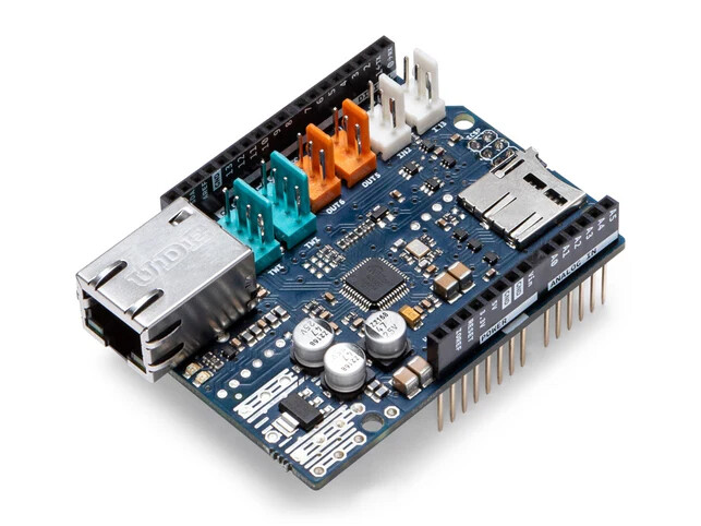
You can plug this shield into the top of any Arduino board that has an UNO or Mega form factor in order to add Ethernet communication capabilities to the board.
You can also purchase prototype shields that simply provide an area of perfboard for you to populate with your own components:

Arduino Uno shield - generic green - side A.jpg by "Retired electrician" - CC0 1.0
I already provided some information above about making electrical connections between components. For the "wire jumpers" I mentioned, you will want to purchase some solid insulated wire. 24 AWG is a good all around gauge as it works well in breadboards as well as for use with perfboard and stripboard.
THANK YOU SO MUCH, this is exactly what I was looking for! As you suggested, a strip board may be a better option for me (since I've already become a bit more familiar with breadboards) though the space in which the circuit will go in is quite small so it will have to be compact.
Okay so I don't think I need a shield for this project, I think the prototype shield was confusing me before because I couldn't differentiate it from a perfboard ![]()
Perfect, our school offers this :)
Thank you so much for all the help!
You are welcome. I'm glad if I was able to be of assistance.
I shared the specific design of stripboard I like to use here:
https://forum.arduino.cc/t/design-tool-for-laying-out-stripboard/1408631/8
Shields are very convenient, but you will probably find you can achieve a smaller design using stripboard or perfboard and one of the more compact board models such as the Nano.