Issues With Multiplexing 16 to 1

Sorry if I posted in the wrong place. I picked this category because it had multiplexing in the name.

I'm working on a project where I hope to use an Uno R3 to make resistance measurements for a cable assembly. Of course, this will be a calculated resistance via a voltage divider. Unfortunately, I can't seem to get the MUX board to work reliably.

I'm using a 16-channel analog multiplexer breakout package based on the 74HC4067. The data reported has little if anything to do with the input value. I can set it for 5V or ground and get the same crazy outputs.

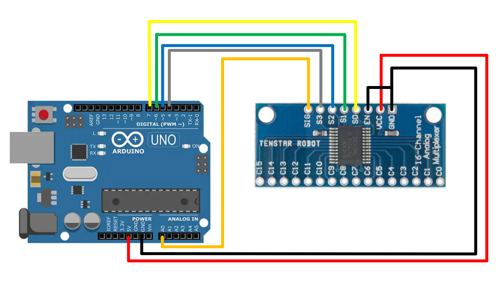
Here is the setup. It's everywhere so I copied it from somewhere:
image

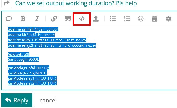
Here is the code I'm using. I've tried so many different variations on the same code I can't remember how many examples I've tried:
`

// 74HC4067 multiplexer (16 to 1)

// control pins output table in array form
// see truth table on page 2 of TI 74HC4067 data sheet
// connect 74HC4067 S0~S3 to Arduino D7~D4 respectively
// connect 74HC4067 pin 1 to Arduino A0   
byte controlPins[] = {B00000000, 
                  B10000000,
                  B01000000,
                  B11000000,
                  B00100000,
                  B10100000,
                  B01100000,
                  B11100000,
                  B00010000,
                  B10010000,
                  B01010000,
                  B11010000,
                  B00110000,
                  B10110000,
                  B01110000,
                  B11110000 }; 

// holds incoming values from 74HC4067                  
byte muxValues[] = {0,0,0,0,0,0,0,0,0,0,0,0,0,0,0,0,};

void setup()
{
  Serial.begin(9600);
  DDRD = B11111111; // set PORTD (digital 7~0) to outputs
}

void setPin(int outputPin)
// function to select pin on 74HC4067
{
  PORTD = controlPins[outputPin];
}

void displayData()
// dumps captured data from array to serial monitor
{
  Serial.println();
  Serial.println("Values from multiplexer:");
  Serial.println("========================");
  for (int i = 0; i < 16; i++)
  
  {
    Serial.print("input I"); 
    Serial.print(i); 
    Serial.print(" = "); 
    Serial.println(muxValues[i]);
    delay(50);
  }
  Serial.println("========================");  
} 

void loop()
{
  for (int i = 0; i < 16; i++)
  {
    setPin(i); // choose an input pin on the 74HC4067
    delay (500);
   muxValues[i]=analogRead(0); // read the vlaue on that pin and store in array
   // int val = analogRead(0);

   //muxValues[i]=(val * 5.0) / 1024.0;
   //muxValues[i] = val; 
  }

  // display captured data
  displayData();
  delay(2000); 
}

I've tried different modules, two different Uno boards, and wired and rewired everything multiple times.

Here is what I know:

  • The program is setting the binary address properly. I verified it with LEDs.
  • Placing 5 VDC or 3.3 VDC on the channel doesn't change anything. I've even tied all unused channels to ground with the same results.
  • I'm getting similar results with all modules I try
  • I get the same results if I set the binary address manually
  • I've tried various pull-up resistors and even voltage dividers to see if it's an issue.

Here is an example of the output data I'm seeing:
image

It's never the same data twice. The boxed channel has a 5V input.

Usually, when this happens to me I smack my head because I missed something very obvious. I have asprin on stand-by for when someone tells me of an obvious solution.

Thanks!

Dave.

Could you please post a schematic of exactly how you have connected the pins. The above picture is hard to interpret.
And a link to the module you are using.

And please post your code in code-tags per forum guidelines. You can update your current post. Code tags is the button that looks like </>

Read the forum guidelines to see how to properly post code and some good information on making a good post.
Use the IDE autoformat tool (ctrl-t or Tools, Auto format) before posting code in code tags.

You can go back and fix your original post by highlighting the code and clicking the </> in the menu bar.
code tags new

It looks like you are writing to port D (pins 0-7) but connected to pins on port B (pins 8-13).

See this page: Arduino Project Hub

Thanks for the response. Sorry for the posting errors....I'm new to the forum.

Here is the link for the module (or one of the several just like it):

I should have drawn this out to begin with. I've tried so many ways, I got confused.......

Very hard to read the module labelling. Link to product, please. Looks like there might be a pin labelled "EN" - if so, that's likely an enable. If not set to the correct voltage level, your input will be floating.
C

I see you've posted more info, and a new diagram. Addresses my comment.

Did you try it with EN high, as well as low? Wouldn't be the first time a description was flat out wrong.
C

Yes. I tried enable as high, low and controlled by another digital line.

This disables serial on pins 0 and 1:

DDRD = B11111111; // set PORTD (digital 7~0) to outputs

This only sets D7~D4 as outputs and leaves pins D3~D0 as is (no change):

DDRD |= B11110000; // set PORTD (digital 7~4) to outputs

Hi,
Welcome to the forum.
Is there a reason you are using direct port comms?

Have you tried the library to do all your port commands?

Thanks.. Tom.. :smiley: :+1: :coffee: :australia:

I downloaded a different library, but I wasn't impressed. Besides, I understand (or at least I thought I did) the raw commands. I'm going to download this library and try again.....

Dave.

All,

First, thanks for the responses. It's funny, I design and build automated test systems for a living and I'm having more trouble with this than I do with an automated system with several pieces of test equipment, relays, and yes, MUX cards.

I tried running the module(s) manually. I'm still getting garbage out in either direction. I've decided there has to be something wrong with the modules. I didn't pay much for them and you get what you pay for.

I ordered more modules from a different vendor. I also ordered brand new 4067 DIP package chips. I'll try those as well.

Thanks again and I'll post how things go.

Dave

Thanks. I did this in an attempt to get the darn things to work. It didn't help to set these back to the original settings.

Red lights are blinking here.

Remember that all pins of a muxer must be within the muxer's supply/ground voltage limits.
Leo..

Thanks. Even when I set this up manually, the darn thing isn't working. I'm powering the module with 5V from the Uno. I'm using it for the ground too. I've tried 3.3 Volts as a binary set as well as 5V.

I even set an r-s latch to control the digital lines, S0-S3. I used a voltage divider to set the binary inputs to various levels from 3.3V, 4V, and 5V.

I'm out of ideas until the new modules arrive. I can't believe I have 5 bad modules, but I can't think of anything else that causes the chips to be utterly uncontrollable.

Thanks!

Dave

DDRD &= ~B11110000; // set PORTD (digital 7~4) to inputs, leave 3~0 unchanged

Seems you have an electronics design problem. Post an schematic of your measuring circuit, along with resistance values of your cable assemblies to better help.

All,

It was the cheapo module causing the problem. The package on the bad one looks significantly different than the one that's working.

Thanks again for all of the assistance.

This topic was automatically closed 180 days after the last reply. New replies are no longer allowed.