Hi all! First post here - I've gotten in to making basic circuits with Arduino boards/LEDs and have been working on the attached LED display (it's a dinosaur, lol) as a gift to my girlfriend. I haven't created a schematic, but the circuit is pretty simple all things considered. There are 56 LEDs total, all controlled by 7 daisy-chained 74HC595 shift registers with a 220ohm resistor for each LED. This all works exactly expected.
I'm posting in hopes for advice on adding basic on/off functionality to the entire circuit (I want to be able to turn the entire thing off by clicking a button, ideally). I've experimented a bit with adding a button as input and then only activating my LED sequence when the button is not pressed, but this has proven to be finnicky at best and not work at worst. I've been researching transistors (I have 2N222 on hand, but can get others if needed), and I believe a transistor(s) could do what I want, but I'm not finding a whole lot of useful information on how to use one to switch LEDs controlled by shift registers. Would I simply place the transistor in line with the data pin (SERIAL pin on 74HC595) going to the Arduino?
Any advice is much appreciated - my basic query is looking for solutions for turning off this entire LED circuit controlled by shift registers. I would love a solution including hardware like transistors, as simply treating a button as a digital input has not worked well thus far.
Even a partial schematic would help. Depending on what kind if LEDs you are using and how they are connected it may be possible to just turn off the power to the LEDs.
All digital ICs need power supply decoupling on their Vcc pins.
If you have 7 ICs, you need 7 decoupling capacitors on their Vcc pins to GND.
These capacitors need to be as physically close to the Vcc pin as possible.
100nF (.1uF) ceramic will suffice.
Lets assume each LED needs 10mA.
56 * 10mA = 560mA (.56A).
This is too much current to take from the Arduino 5v pin.
There are many ways but it depends on how they are wired and how much time you have to setup and accomplish the task. Without an annotated schematic showing exactly what you have I could only guess and probably will be wrong. As others have asked if you are serious draw a schematic. If you want to do it with CAN (Computer Aided Design) software KiCad is very good and is free for the downloading.
Thank you for the advice and patience. I'm new to the electronics and have been picking this up as a hobby, so there's tons I don't know. I am learning how to draw schematics now so I can produce a schematic for this project. No restraint on time, just trying to learn everything as accurately as possible!
I appreciate the advice, Larry. This is all very new to me - I'm learning how to draw schematics now and will update this post with the schematic once I create it. Could you give a little more info on why I should have those capacitors? The LEDs are lighting without, so I just want to make sure I understand their purpose. Additionally, would I just wire these capacitors in-line with the VCC pins?
Digital ICs demand high currents for short periods of time.
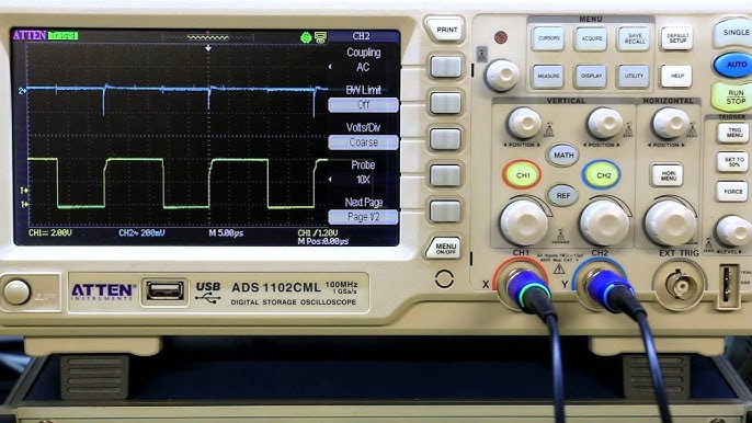
If you look a the voltage on the Vcc pin with a scope you can see what these demand currents can do to 5v power to the IC.
Great job. As stated by @jim-p use the OE\ pin to turn the outputs on and off. If that pin is low the LEDs should light, when High they will turn off. Also put a pull up resistor on the processor pin so they remain off during power on, reset and setup().
Thanks so much for the very detailed advice! Sorry for the poor res - a better picture is attached. What exactly do you mean when you say the LED current is too much for the Arduino to supply? Are the capacitors the solution here, or are you saying the Arduino is flat-out unable to supply that much power? I'm not well versed at all in current/load calculations like that and what exactly they mean, but I would love to learn more. Additionally, when you say I should place the caps "close to all the 5v pins", do you mean literally physically close, as in close as physically close as possible to the actual pin 14? What difference is there if the capacity is in line with the pin but a couple inches away? Thanks again SO much for all the help!
This is great advice @gilshultz@jim-p - thank you both! My OE pins are currently all just going to common ground. If I'm understanding correctly, you are saying that instead of sending these all to ground, I can wire them all together and send this connection to a new pin on the Arduino? This makes sense why you say to set the pin to low - I guess that essentially serves the same purpose as the pin being grounded as it currently is? Also, do you have a recommendation for the resistance value I should use for the pull up resistor?
You were not mistaken in thinking the line represents the positive side, the problem is there's more than one way to interpret 'the positive side'. It means that end of a diode will be the positive output. I imagine you are confused. Forget that. The arrow (triangle) points in the direction of conventional current flow, in other words towards negative.
Yes exactly. Set the pin LOW to enable the LEDs and HIGH to disable them. Never tried this but you may be able to use PWM on the OE pins to adjust brightness.