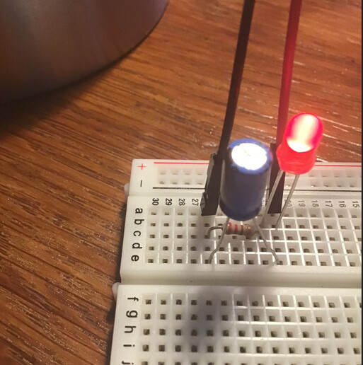
I tested a simple circuit with a red LED, a 220 Ohm resistor and a 100uF 25V capacitor. The capacitor is connected across the LED and the resistor. When I disconnect the power the LED goes off immediately, i.e., it does not take a few seconds to fade. It behaves as if the capacitor does not store any energy. I made some napkin calculations and got that the amount of time the LED stays on is about 0.01seconds which, if I am right, should explain why I do not see the LED fading. So, I have a few questions:
What capacitance do I need to be able to see the LED fading?? Would 1000uF be sufficient or need higher??
Would a 10000uF Electrolytic Capacitor allow me to see a longer fading??
What is a Radial Electrolytic Aluminum Capacitor??
What is the difference between Aluminum High Frequency Electrolytic Capacitor and an Aluminum Low Frequency Electrolytic Capacitor?
What's the advantage of Low Impedance capacitors??
If I wanted to use the capacitor as a filter or to de-bounce a button, which capacitor type will be best??
Any other suggestions would be much appreciated.
Sorry for the many questions and many thanks in advance!! AA
What do you mean by this? Are you physically disconnecting the power source at its output terminal(s), or using a switch that is wired in series with the power source?
Or are you powering the LED using an Arduino digital output pin, and then switching the pin state from HIGH to LOW? If this is what you're doing, then no capacitor is going to let you see any gradual fading, and you are at high risk of damaging the output pin on your board.
Even if you are using the first approach, whatever power source you are using is effectively being short-circuited each time that you are re-connecting the power source. For example, with a 5-V source, and a 0.1-Ω ESR, you may be drawing as much as 50 A of current from the power source whenever you connect it to an uncharged capacitor.
So, if the capacitor is not charged (LED is dark), and you then connect the red wire between Arduino 5V and your breadboard as shown, you will briefly be pulling 5–50 A of current from the 5-V pin on your Arduino as the capacitor charges up. This may damage your Arduino, and if your Arduino is powered by a USB cable from a computer, it may also damage your computer.
The larger you make the capacitor, the more dangerous this becomes.
Yes, when the capacitor is uncharged, the only impedance to the inrush of charge from your 5-V pin is the internal resistance of the capacitor ("equivalent series resistance", or ESR), which is typically very small (0.1–1 Ω).
An analogy would be routing a very short tube from the bottom of a kiddie pool to the bottom of an adjacent bucket (of similar height to the pool). If the bucket is empty, there will be an inrush of water into the bucket, limited only by the fluid drag resistance within the short piece of tubing (analogous to the internal resistance of the capacitor). If the resistance is small, then the flow rate of water from the kiddie pool (analogous to current flow from the Arduino 5_V source) will be large.
Yes, if you know the ESR value in ohm (R), and you are applying a voltage V, then the current drawn (I) will be:
I = V/R
A cursory search of the reference materials did not turn up any definitive information about the maximum allowed current draw from the 5V pin, but I would assume it's in the range 100–500 mA. In that case, a 50-Ω series resistor should limit the current to safe-ish levels.