I know I said ... that I will not do high speed robot runs without making use of sensors.
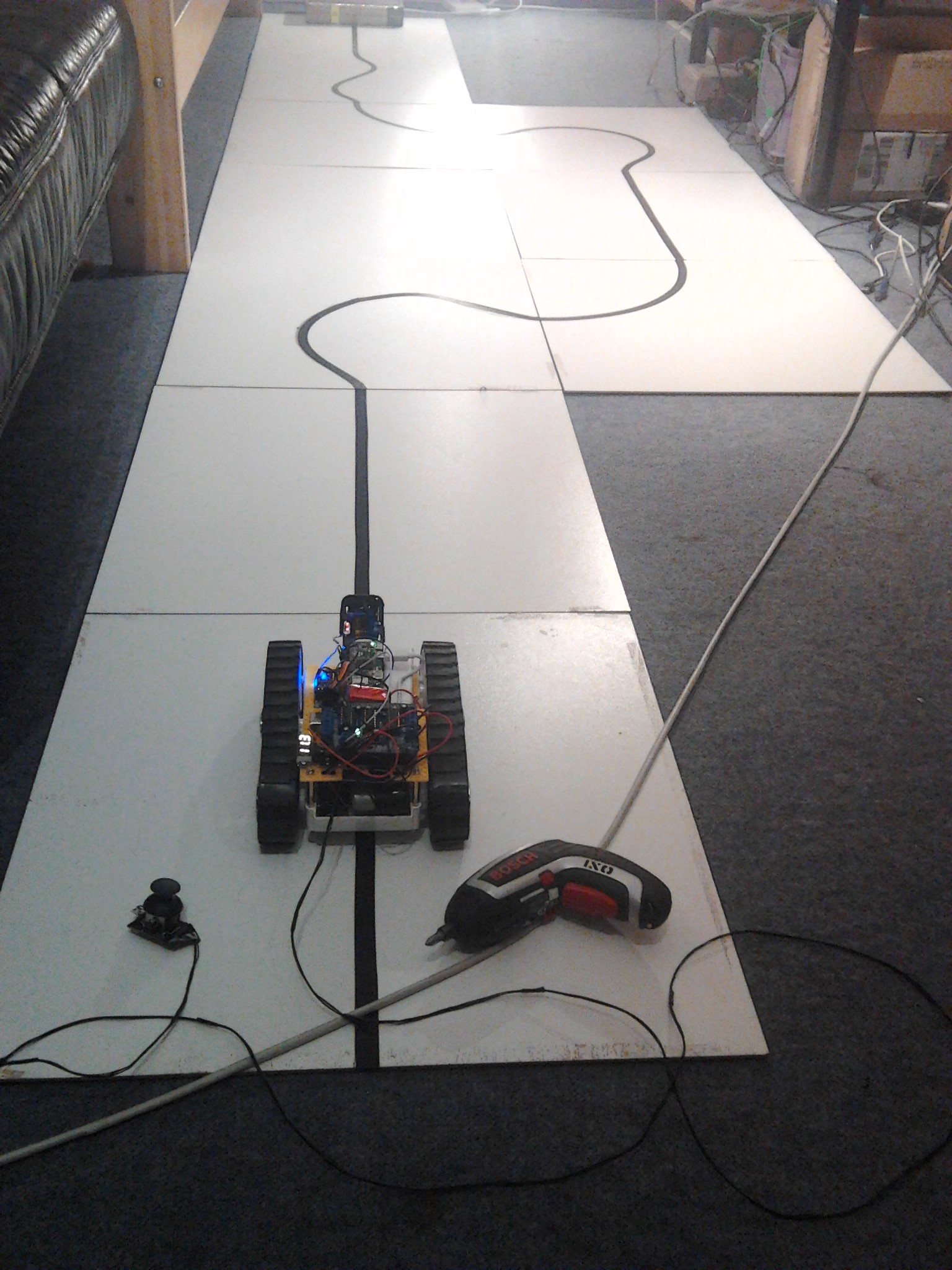
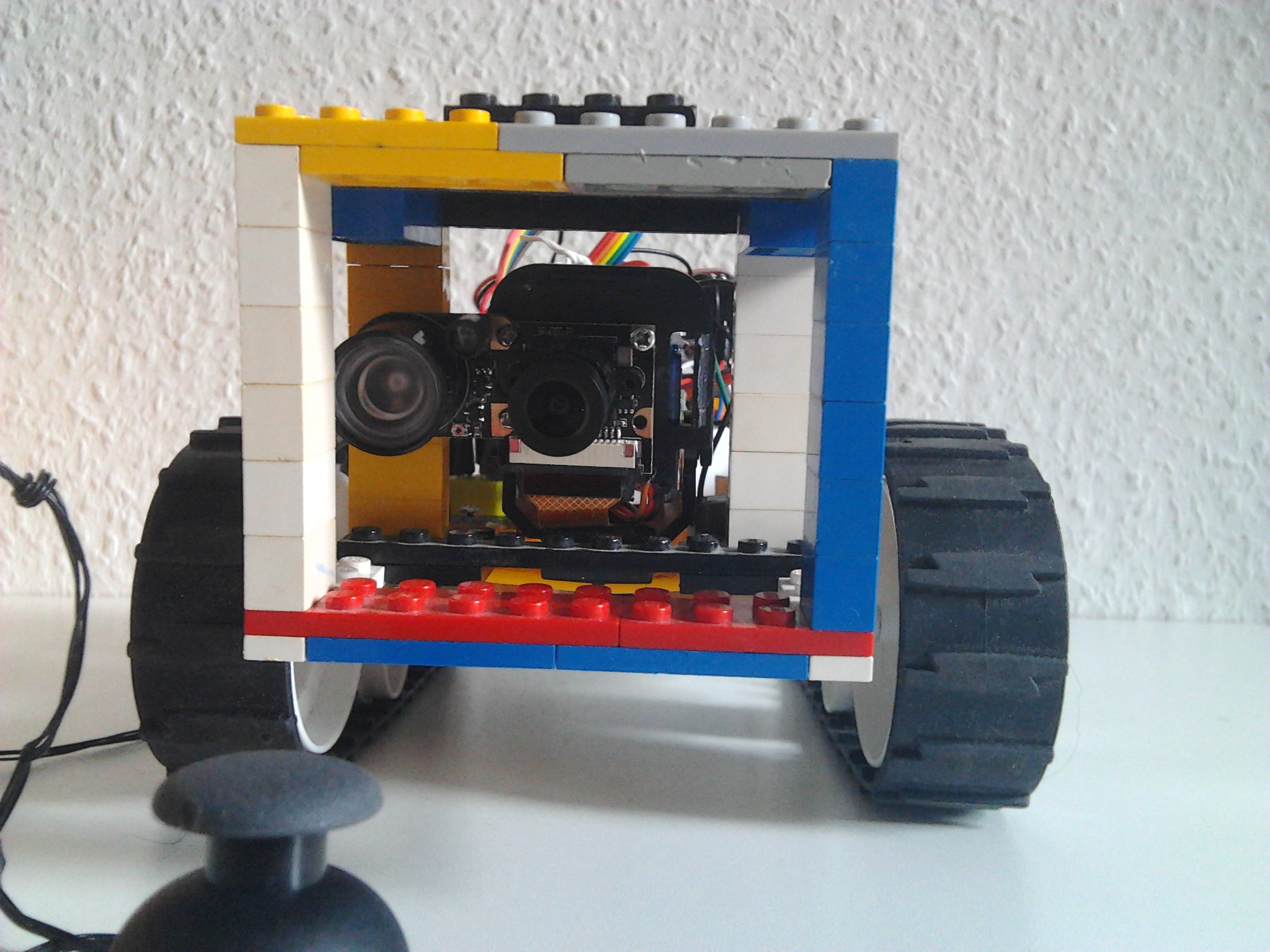
But after tramping on joystick cable yesterday the test platform was "free of cords".
So I programmed full speed 180° turn(s) again and made two videos of the same run.
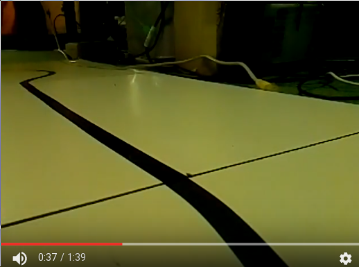
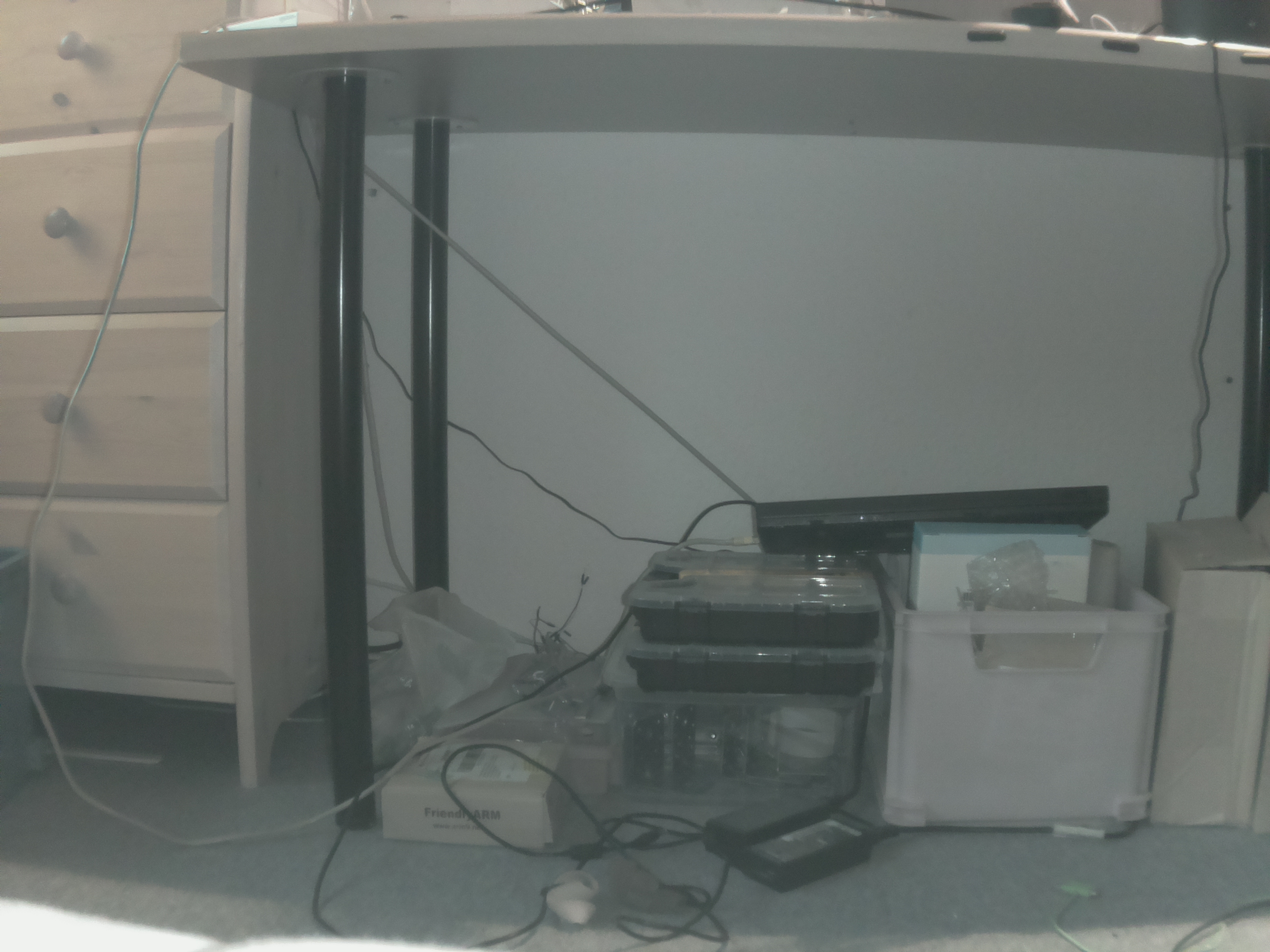
The 1st with Android camera, it shows what happened, including sound (in youtube video).
This shows what happened in correct speed:
 Android phone video")
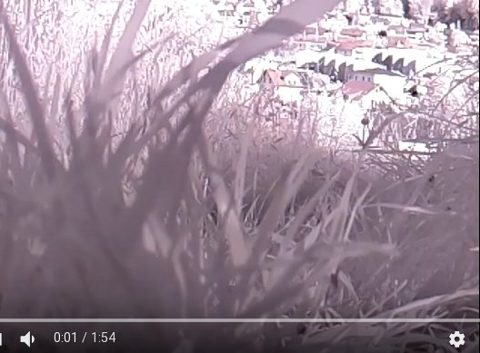
This is 2nd video (90fps) from robot onboard Raspberry camera (slowed down by factor of 90/25=3.6):
 robot onboard 90fps video")

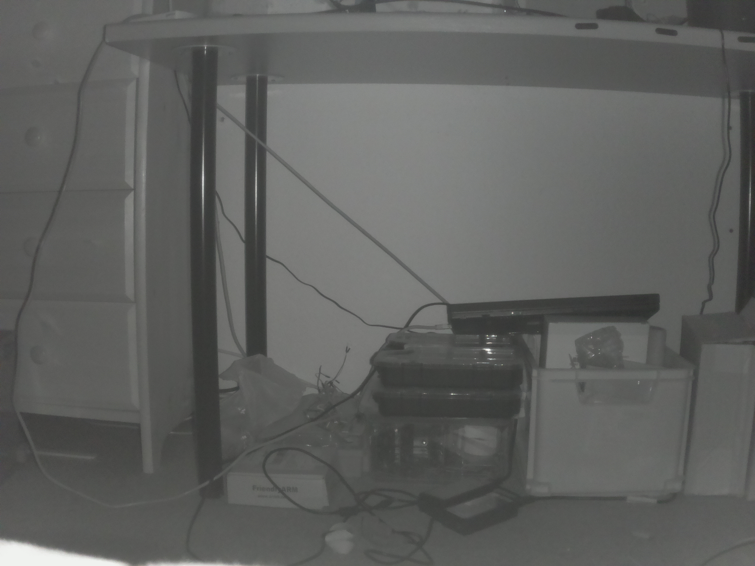
The room was lit from 3 lights, and Android video shows bright frames.
But that was not enough for 90fps video, looks quite dark.
So what should have happened in videos:
- robot accelerates from stand still to full speed and keeps it
- short before dog chew bone do full speed U-turn
- keeping full speed drive back
- do a second full speed U-turn
- keep full speed drive back
- full stop
As you can see the 1st U-turn was overshooted.
Then the robot drove into room crossing ethernet cable.
That cable reduced robot turn speed and this time U-turn did not reach 180°.
Slowed down the robot then drove over some cables until stop.
Hermann.
For taking the video on Raspberry Pi Zero I used new "camera_slave.c" posted here:
https://www.raspberrypi.org/forums/viewtopic.php?f=43&t=181504
This is the sketch used for the videos:
#include <AFMotor.h>
#include <Servo.h>

Servo myservo;

AF_DCMotor ml(4); AF_DCMotor mr(3);

#define m 255

void setup() {
  int i;

  Serial.begin(57600);

  pinMode(10, OUTPUT);
  digitalWrite(10, LOW);

  ml.setSpeed(0);  mr.setSpeed(0);
  ml.run(RELEASE); mr.run(RELEASE);

  ml.run(FORWARD);  mr.run(FORWARD);

  myservo.attach(9);
  myservo.write(90);
  delay(500);
  myservo.write(50);

  delay(1500);

  digitalWrite(10, HIGH);
  delay(500);

  for(i=128; i<m; ++i) {
    ml.setSpeed(i); mr.setSpeed(i);
    delay(6);
  }
  delay(400);
  ml.run(BACKWARD);
  delay(320);
  ml.run(FORWARD);
  delay(1000);
  ml.run(BACKWARD);
  delay(320);
  ml.run(FORWARD);
  delay(1000);
  ml.setSpeed(0); mr.setSpeed(0);

  digitalWrite(10, LOW);
}

void loop() {
}


 joystick controlled caterpillar robot line following")


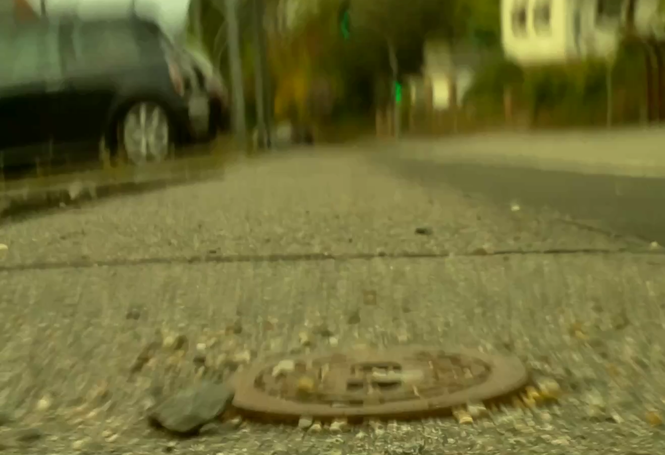


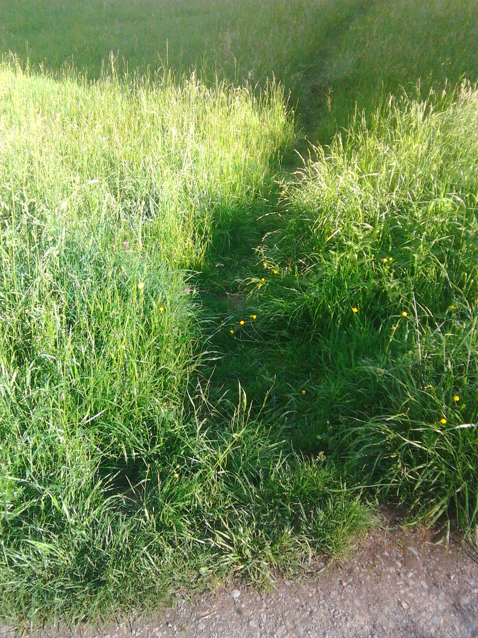
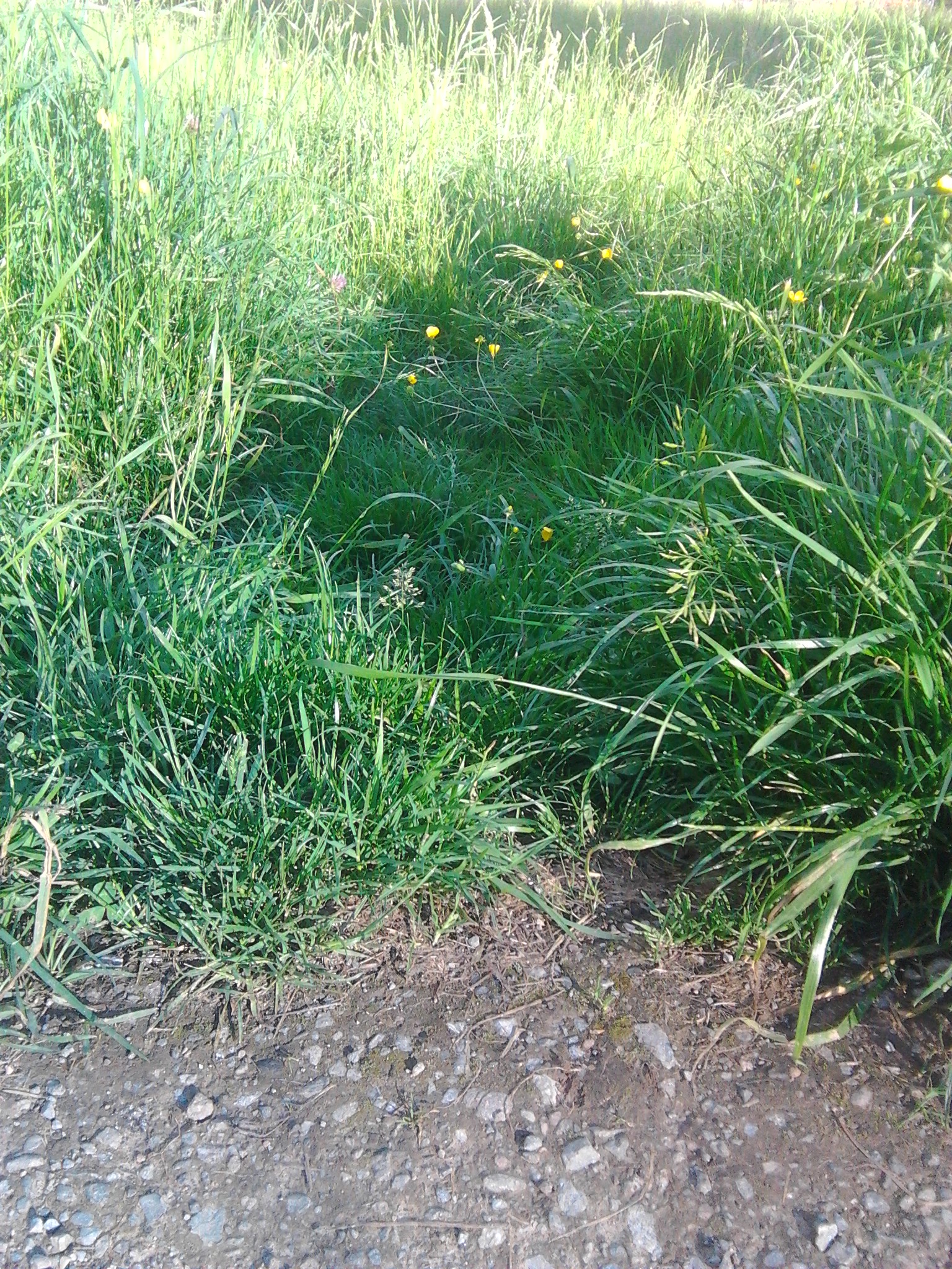
 grassy hiking traill")


")


