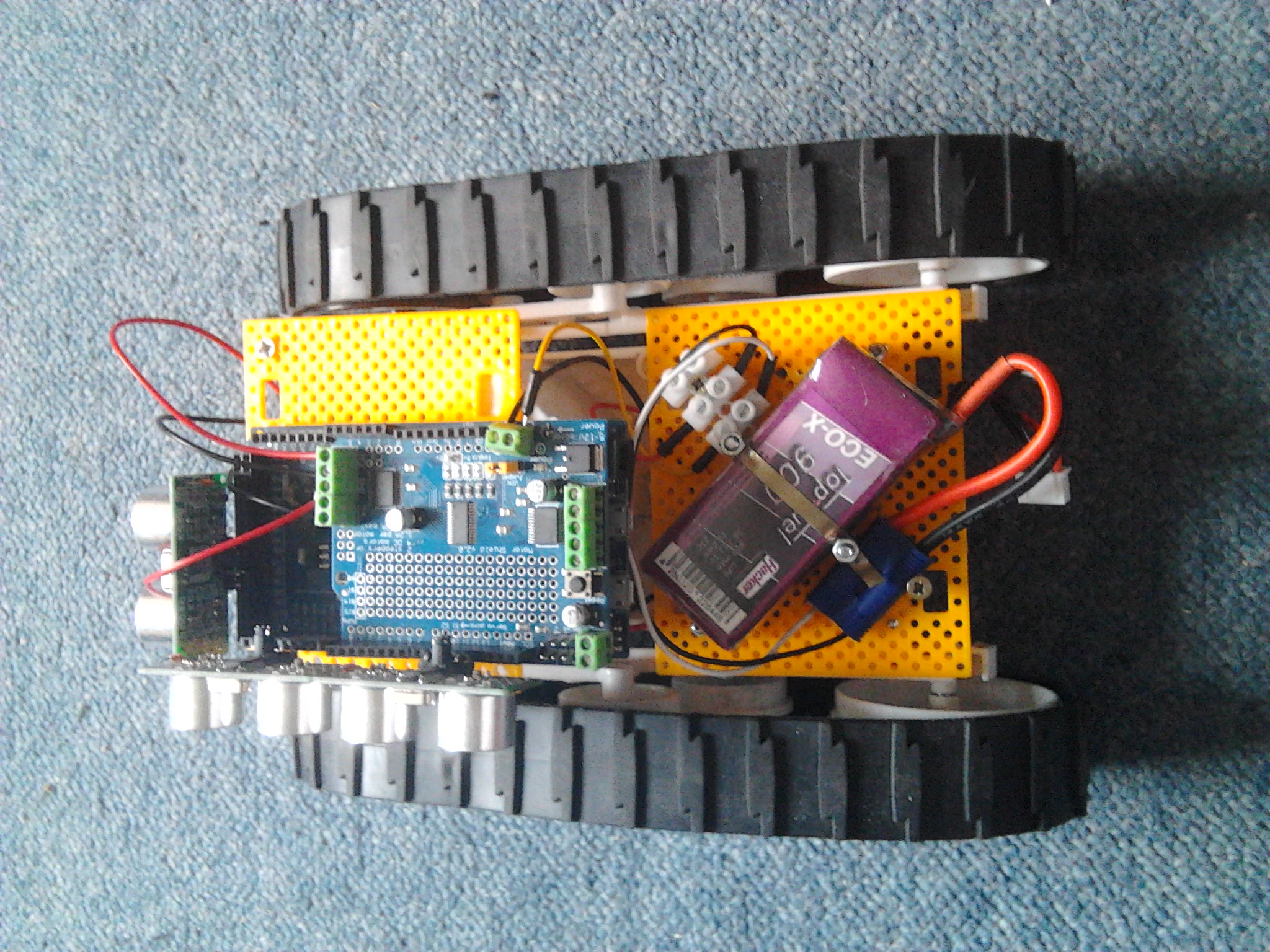
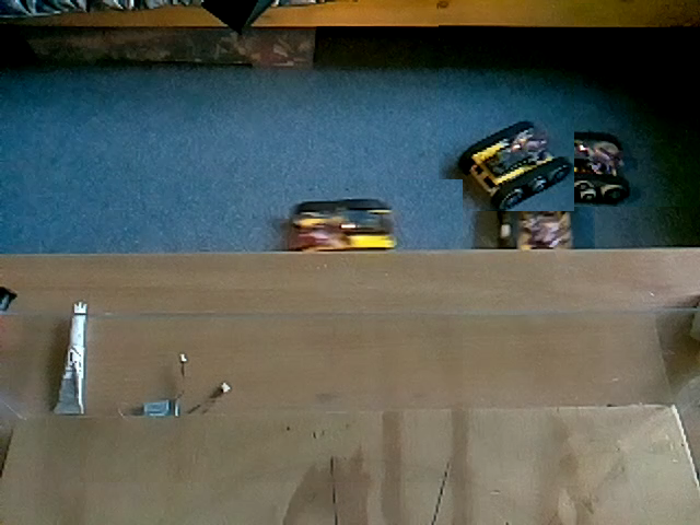
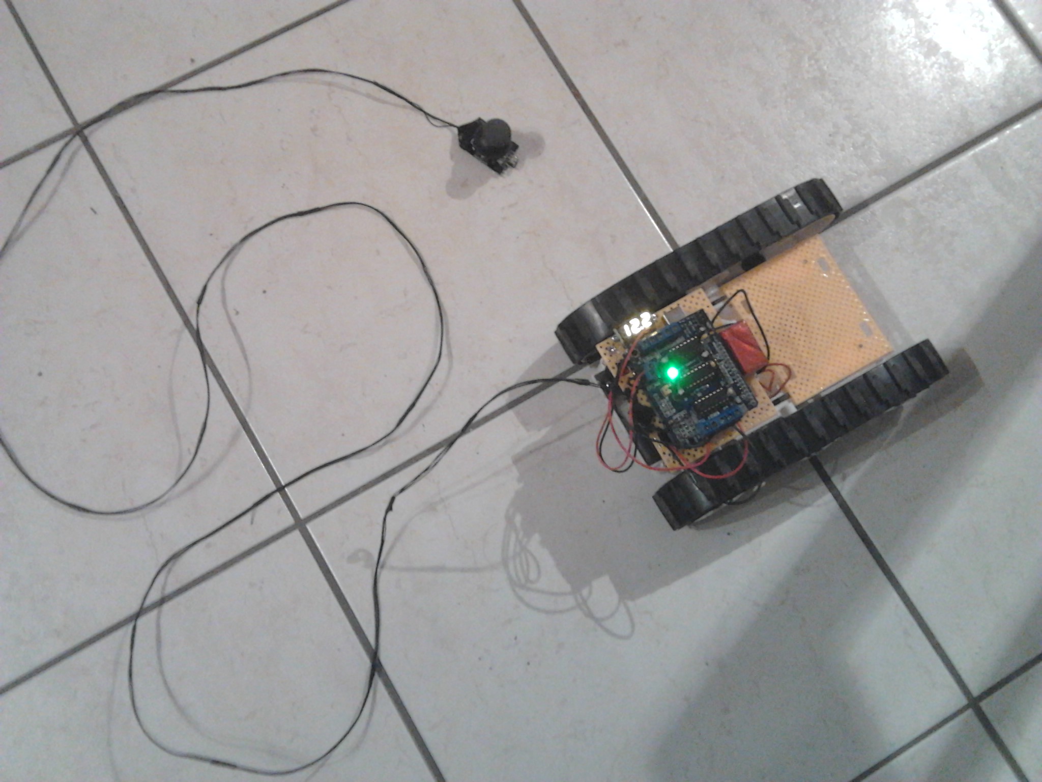
The robot platform sometime did funny things, here it took (joystick) control away from me 

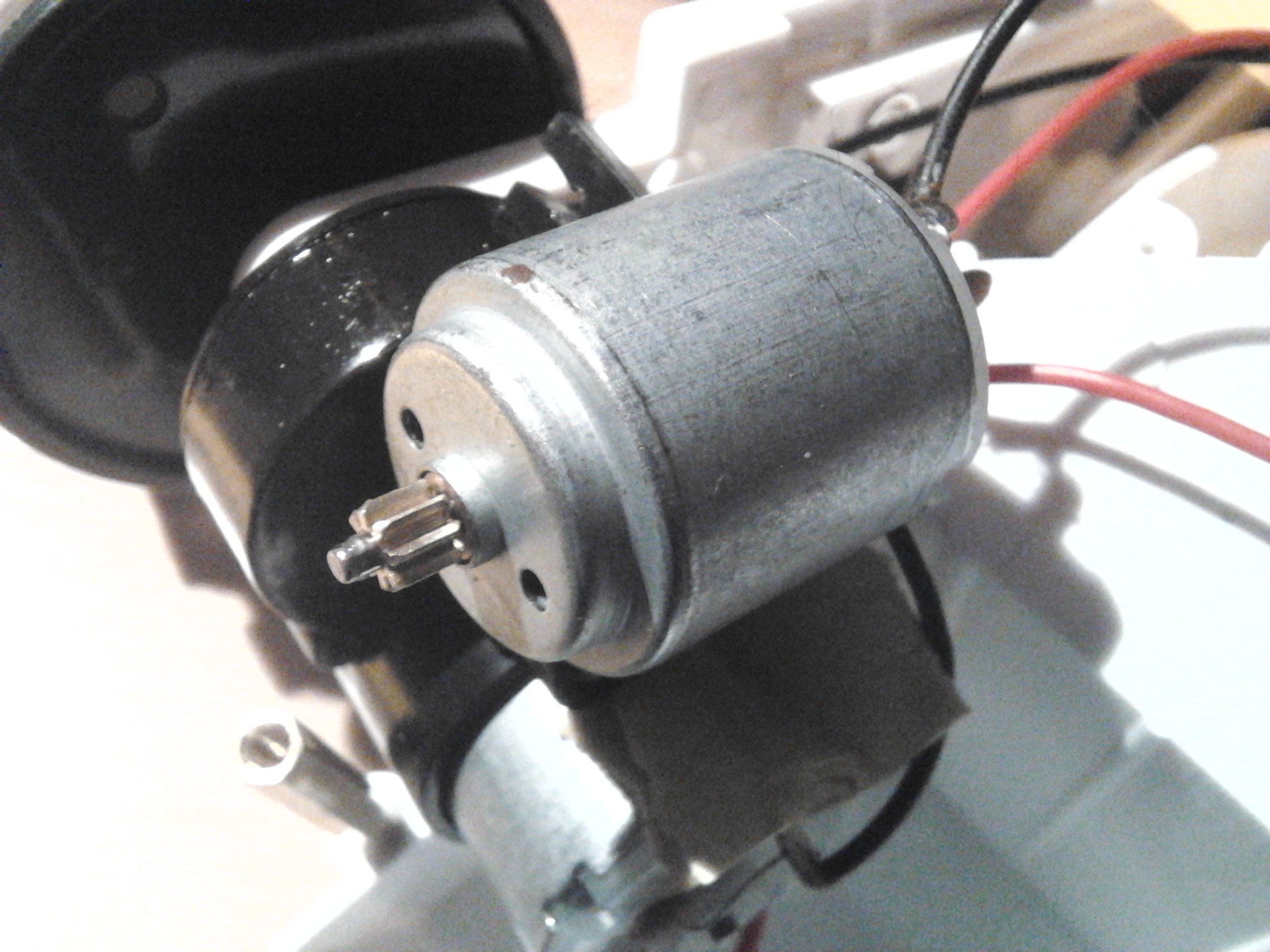
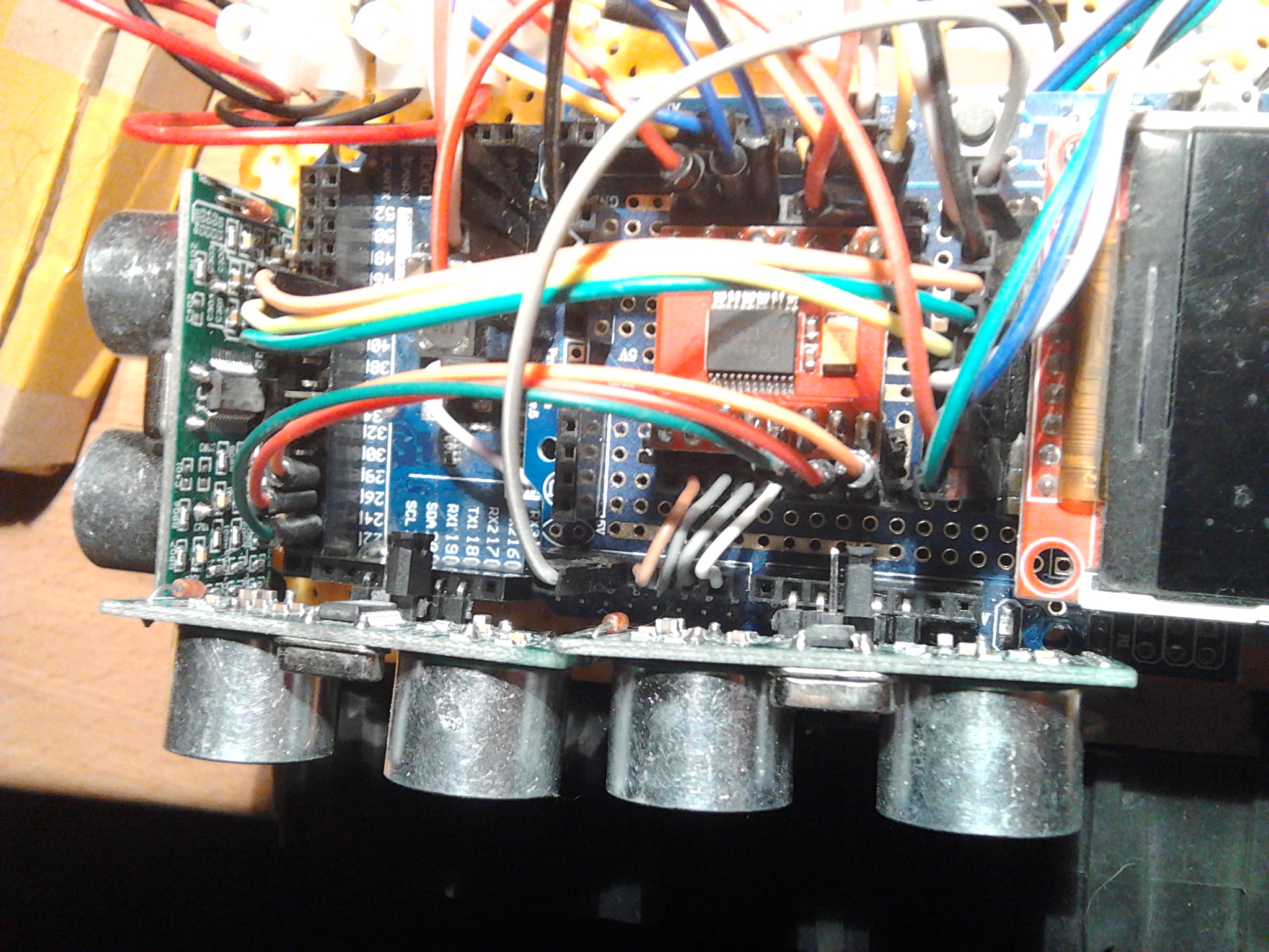
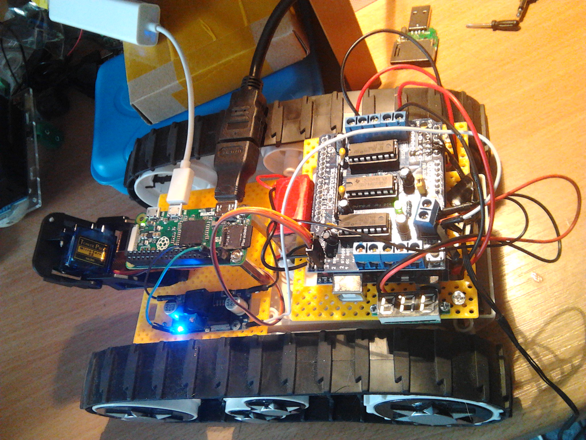
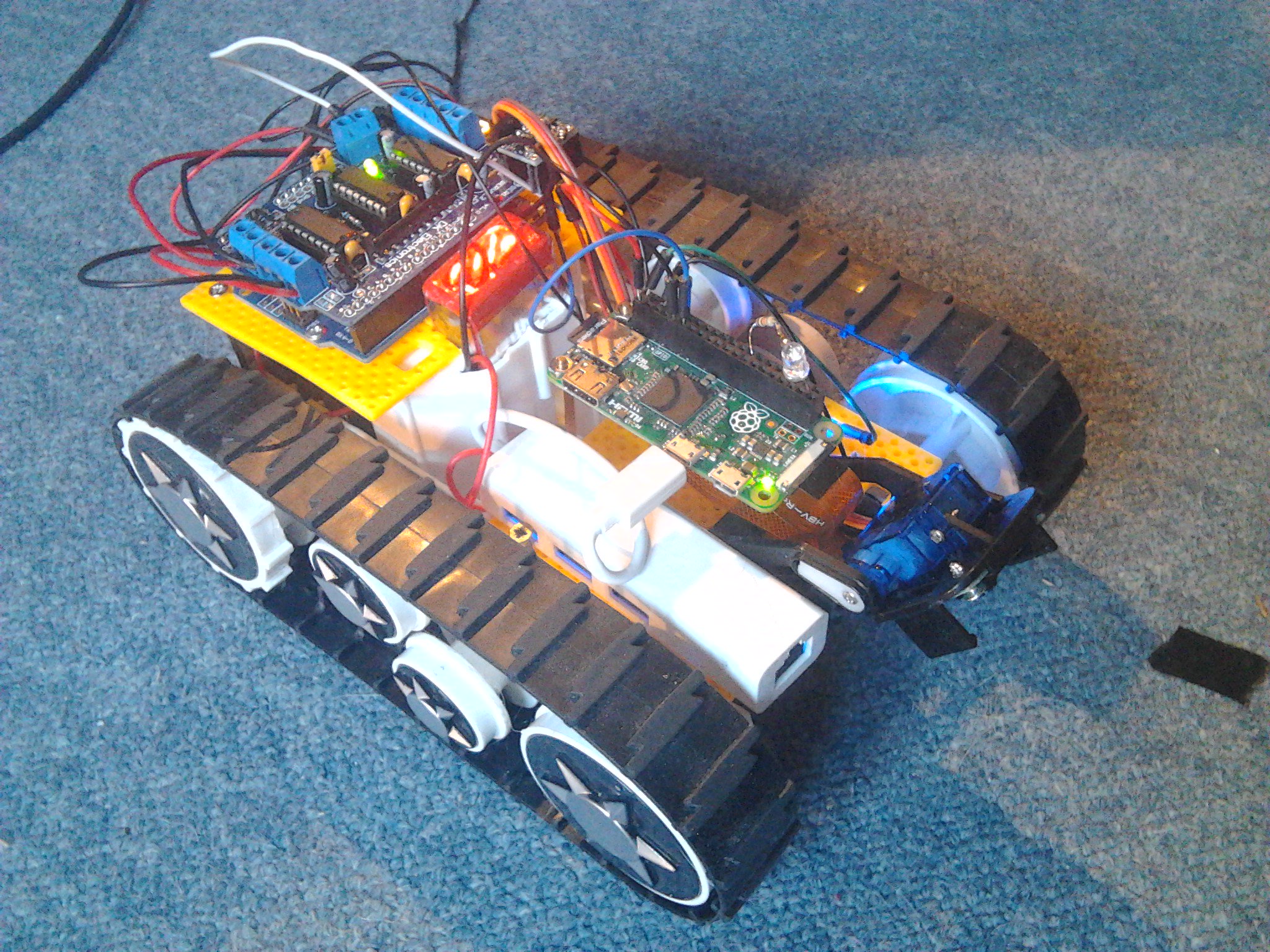
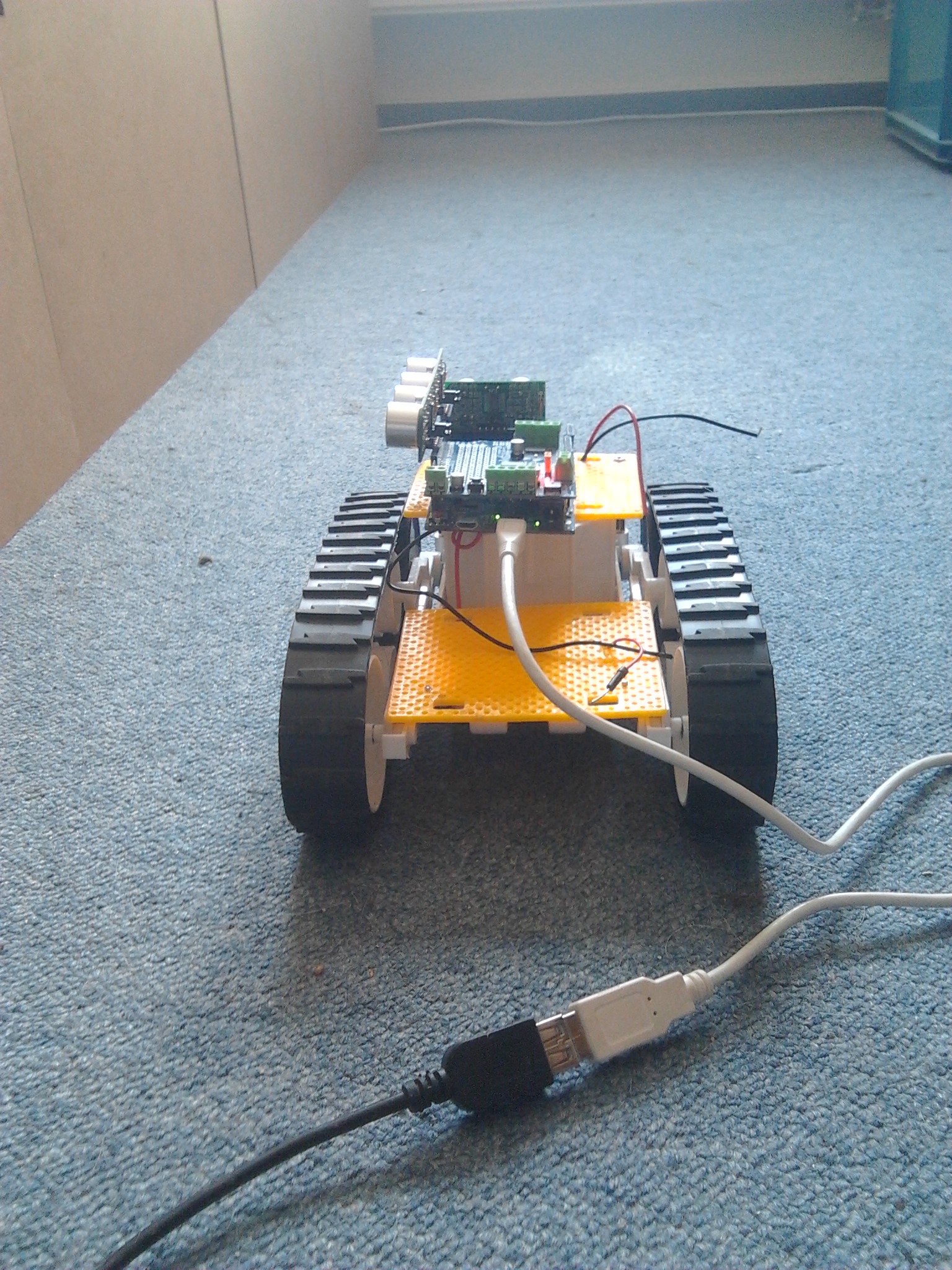
Next I found out how to mount tilt system with Raspberry camera, and the Raspberry Pi Zero itself on two long spacers, so that the flexible camera cable has pace below Pi Zero to move fore and back. I learned that the Pi Zero could not be powered by Arduino Uno GND/5V – it works for some time, but whenever Arduino Uno makes camera servo move, the Pi Zero did reset. So I did power Pi Zero wth 5V from LM2596:

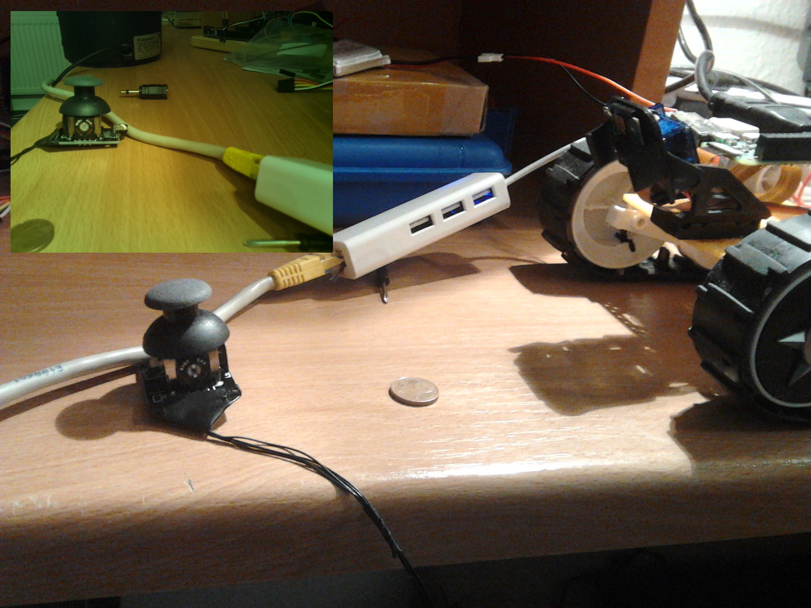
Experiments revealed that camera inclination of 35° was good to see ground in front from 8cm up to 1m ahead:

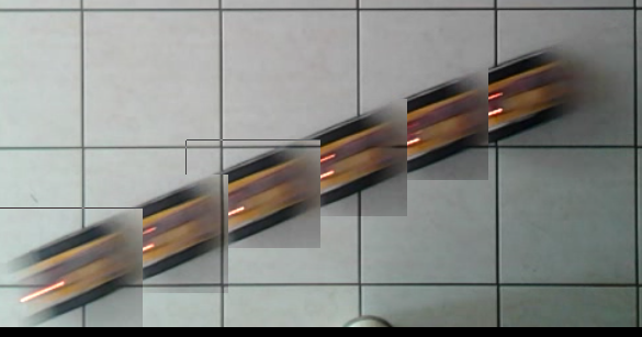
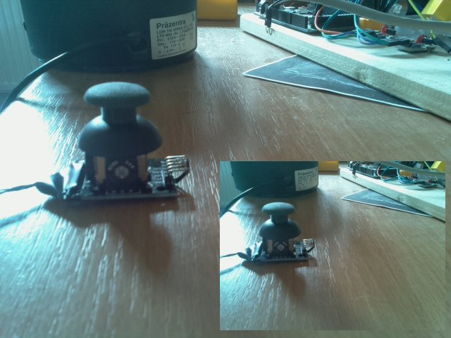
I have always done 90fps slowmo videos with 640x480 resolution, because I could. In between I realized that 320x240 @90fps might be sufficient as well, at least the lower right 320x240 photo looks not worse than total 640x480 photo:

For some reason the video taking only works when USB to ethernet adapter was "onboard"?!?

I bought a Pi Zero W when it was first available, and it worked really nice. I killed it after one week, most likely by 5V cable unplanned contact with Zero W pins. I am waiting for my 2nd Pi Zero W to arrive next week -- that way I will definitely not need an onboard ethernet anymore (and streaming video for 1st person view will become possible).
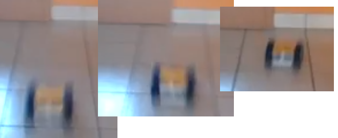
This is first "fast" driving 90fps slowmo video taken by the onboard Raspberry Pi Zero and camera. It is surprisingly "stable", I was not sure what the high speed caterpillar platform movement would do to the video. Remember that the video gets played slowed down by factor 90/25=3.6:

I am not sure whether there was a wall crash at the end of first fast forward phase, or whether robot stopped just before the wall. If, then it was the camera tilt system.
Speeds (determined by counting frames bewteen the tape stripes on ground 50 apart):
- 1.40m/s from 0-50cm (32 frames)
- 1.87m/s from 50-100cm (24 frames)
- 2.14m/s from 100-200cm (2×21 frames)
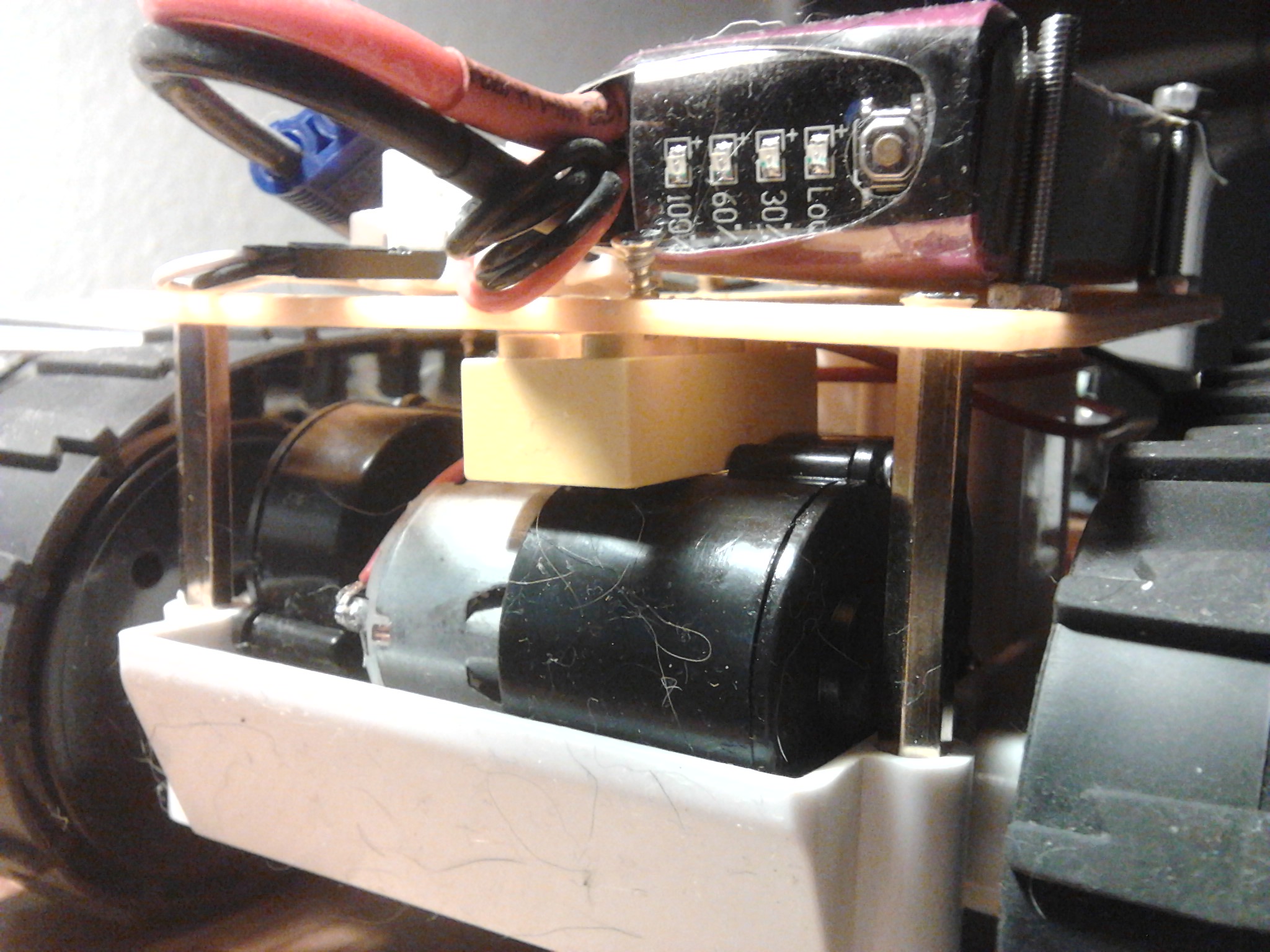
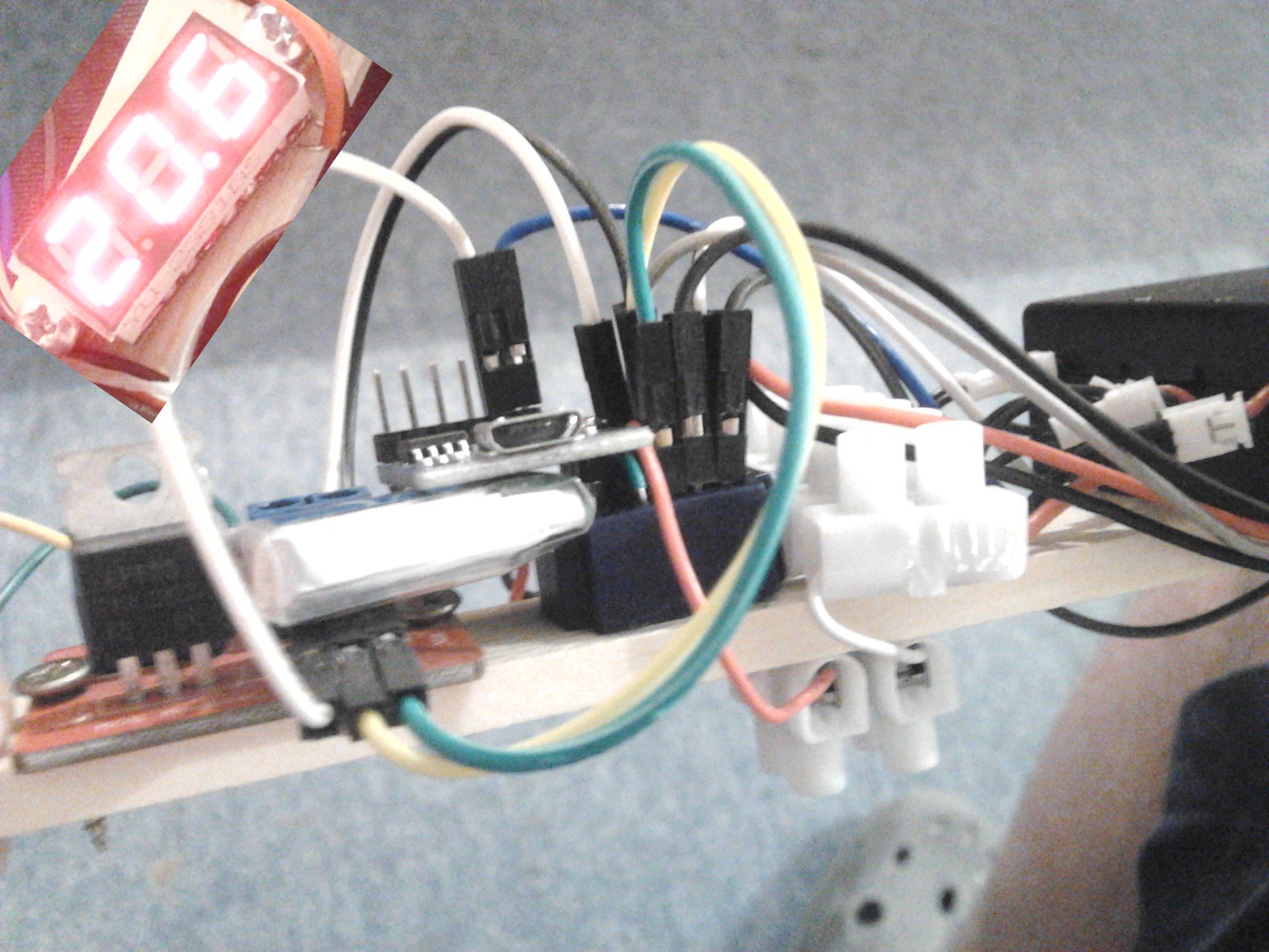
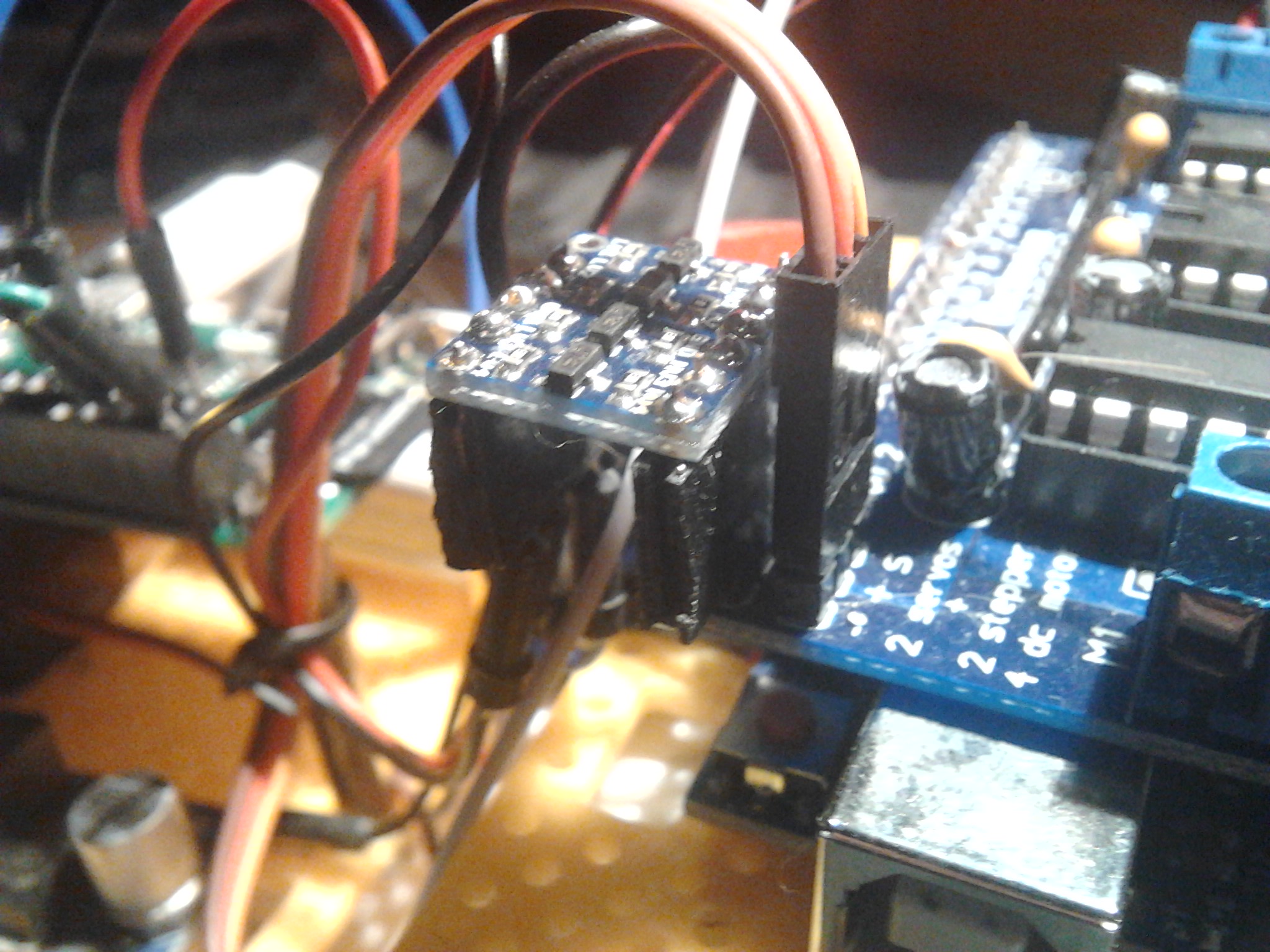
I use the Pi Zero in "slave" mode, and the Uno signals when a video should be taken. Therefore a 5V/3.3V level shifter was necessary. I do use Servo2 pins for controlling the camera servo. But Servo1 pins (D10/5V/GND)were available. I did solder female headers below the level shifter and was able to just put the level shifter onto Servo1 pins:

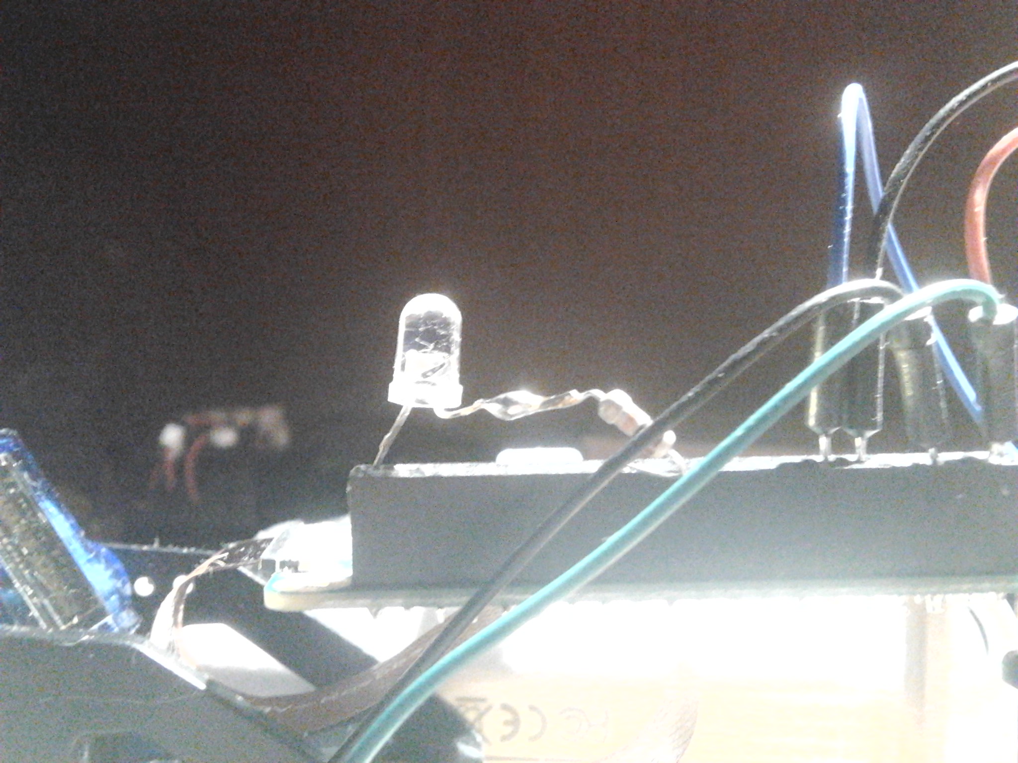
Finally I added a soldered LED/1kΩ pair to Pi Zero, that is turned on by Pi while raspivid runs:

I changed the previous sketch for robot platform joystick control only slightly. The triggering is done in "setup()", so that the request for taking a video is done by pressing reset key:
#include <AFMotor.h>
#include <Servo.h>

Servo myservo;

AF_DCMotor ml(4); AF_DCMotor mr(3);

int x = 0, y = 0, y0 = 506, x0 = 490, Y, X;

void setup() {
  Serial.begin(57600);

  ml.setSpeed(0);  mr.setSpeed(0);
  ml.run(RELEASE); mr.run(RELEASE);

  myservo.attach(9);
  myservo.write(60);

  // signal Raspbery Pi zerop to start camera (raspivid ...)
  pinMode(10, OUTPUT);
  digitalWrite(10, HIGH);
  delay(2000);
  digitalWrite(10, LOW);
}

void loop() {
  x = analogRead(A0); y = analogRead(A5);

  if (y < y0) {
    Y = map(y0 - y, 0, y0, 0, 255);
    ml.run(BACKWARD); mr.run(BACKWARD);
  } else {
    Y = map(y, y0, 1023, 0, 255);
    ml.run(FORWARD);  mr.run(FORWARD);
  }

  if (x < x0) {
    X = map(x0 - x, 0, x0, Y, 0);
    ml.setSpeed(X); mr.setSpeed(Y);
  } else {
    X = map(x, x0, 1023, Y, 0);
    ml.setSpeed(Y); mr.setSpeed(X);
  }

#if 0
  Serial.print("Y = " );   Serial.print(Y);
  Serial.print("\t X = "); Serial.println(X);
#endif

  delay(2);
}
On the Raspberry side this is the "camera_slave" bash script that does what is needed, and it gets started in .bashrc after reboot:
pi@raspberrypi02:~ $ tail -3 .bashrc
# ~/clkl

./camera_slave
pi@raspberrypi02:~ $ cat camera_slave
#!/bin/bash

while (true)
do
  if ((`gpio read 0`))
  then
    while ((`gpio read 0`))
    do
      sleep 1
    done

    f=`date +%Y-%m-%d_%X`.h264
    gpio write 11 1
    raspivid -w 640 -h 480 -fps 90 -t 5000 -o "$f"
    gpio write 11 0
  else
    sleep 1
  fi
done
pi@raspberrypi02:~ $
Hermann.


 90fps slowmo video, from caterpillar robot onboard Raspberry camera")

 90fps slowmo video, from caterpillar robot onboard Raspberry camera")
