I can't seem to upload the sketch/code to my sons Uno R4 Minima. the IDE software says its complete but my TX/RX lights done light up. when i move joysticks to control thruster nothing happens. When i'm in the ide software and clickserial monitor i can see when i move joystick on both. This is my first time doing anything with this for my sons science project. I need some help i think
Your problem description does not seem to indicate an upload problem as you can "see information" in the serial monitor. Therefore your topic has been moved to a more suitable location on the forum.
Since it is your sons science project, you might consider letting him solve the problem. I generally find young people understand this better than older people.
Code does exactly as programmed, so your code is wrong.
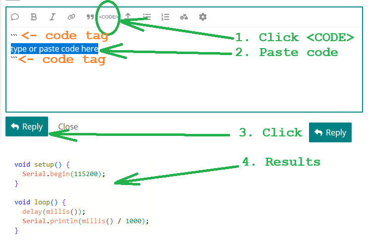
Please post the code.
/*
Code to control an ROV with left and right motors
using "tank" steering with two joysticks
*/

// define pins
const int joyLpin = A0;     // left joystick
const int joyRpin = A1;     // right joystick
const int motorLfwd = 7;   // left motor forward pin
const int motorLbck = 8;    // left motor backward pin
const int motorLen = 10;   // left motor enable pin
const int motorRfwd = 9;    // right motor fwd pin
const int motorRbck = 12;    // right motor backward pin
const int motorRen = 11;   // right motor enable pin

// variables
int joyL;                   // left joystick reading (0-1023 from ADC)
int joyR;                   // right joystick reading (0-1023 from ADC)
int joyLneutral;            // left joystick neutral position
int joyRneutral;            // right joystick neutral
const int deadzone = 20;    // joystick "dead zone" to prevent drift
int motorLspeed;            // left motor speed (0-255 for PWM)
int motorRspeed;            // right motor speed (0-255 for PWM)

void setup() { // code that only runs once
  // set motor control pins as outputs
  pinMode(motorLfwd,OUTPUT);
  pinMode(motorRfwd,OUTPUT);
  pinMode(motorLbck,OUTPUT);
  pinMode(motorRbck,OUTPUT);
  pinMode(motorLen,OUTPUT);
  pinMode(motorRen,OUTPUT);
  // calibrate joysticks
  joyLneutral = analogRead(joyLpin);
  joyRneutral = analogRead(joyRpin);

  Serial.begin(9600);

}

void loop() {  // code that loops forever
  // read joysticks
  joyL = analogRead(joyLpin);
  joyR = analogRead(joyRpin);

  Serial.print("Left: ");
  Serial.print(joyL);
  // set left motor direction and speed
  if((joyL-joyLneutral) < -deadzone){ // joystick pushed forward
    digitalWrite(motorLfwd,HIGH);
    digitalWrite(motorLbck,LOW);
    motorLspeed = map(joyL,joyLneutral,0,0,255);
    Serial.print(" fwd ");
  }
  else if((joyL-joyLneutral) > deadzone){
    digitalWrite(motorLfwd,LOW);
    digitalWrite(motorLbck,HIGH);
    motorLspeed = map(joyL,joyLneutral,1023,0,255);
    Serial.print(" back ");
  }
  else{
    digitalWrite(motorLfwd,LOW);
    digitalWrite(motorLbck,LOW);
    Serial.print(" stop ");
    motorLspeed = 0;
  }
  Serial.print(motorLspeed);

  Serial.print(" Right: ");
  Serial.print(joyR);

  // set right motor direction and speed
  if((joyR-joyRneutral) < -deadzone){ // joystick pushed forward
    digitalWrite(motorRfwd,HIGH);
    digitalWrite(motorRbck,LOW);
    motorRspeed = map(joyR,joyRneutral,0,0,255);
    Serial.print(" fwd ");
  }
  else if((joyR-joyRneutral) > deadzone){
    digitalWrite(motorRfwd,LOW);
    digitalWrite(motorRbck,HIGH);
    motorRspeed = map(joyR,joyRneutral,1023,0,255);
    Serial.print(" back ");
  }
  else{
    digitalWrite(motorRfwd,LOW);
    digitalWrite(motorRbck,LOW);
    Serial.print(" stop ");
    motorRspeed = 0;
  }
  Serial.println(motorRspeed);
  analogWrite(motorLen,motorLspeed);
  analogWrite(motorRen,motorRspeed);

}
so i bought a different adriuno board, uno R3 instead of the Minima R4. The code now seems to download to card, i have the tx/rx lights on. But when i push joystick the thrusters will not turn. I have check wiring multiple times, I'm kind of at a loss. Either the brand new thrusters are bad or something is wrong with the code that i do not understand.
No part of your code calls "thrusters"
/*
Code to control an ROV with left and right motors
using "tank" steering with two joysticks
*/
// define pins
const int joyLpin = A0; // left joystick
const int joyRpin = A1; // right joystick
const int motorLfwd = 7; // left motor forward pin
const int motorLbck = 8; // left motor backward pin
const int motorLen = 10; // left motor enable pin
const int motorRfwd = 9; // right motor fwd pin
const int motorRbck = 12; // right motor backward pin
const int motorRen = 11; // right motor enable pin
// variables
int joyL; // left joystick reading (0-1023 from ADC)
int joyR; // right joystick reading (0-1023 from ADC)
int joyLneutral; // left joystick neutral position
int joyRneutral; // right joystick neutral
const int deadzone = 20; // joystick "dead zone" to prevent drift
int motorLspeed; // left motor speed (0-255 for PWM)
int motorRspeed; // right motor speed (0-255 for PWM)
void setup() { // code that only runs once
// set motor control pins as outputs
pinMode(motorLfwd,OUTPUT);
pinMode(motorRfwd,OUTPUT);
pinMode(motorLbck,OUTPUT);
pinMode(motorRbck,OUTPUT);
pinMode(motorLen,OUTPUT);
pinMode(motorRen,OUTPUT);
// calibrate joysticks
joyLneutral = analogRead(joyLpin);
joyRneutral = analogRead(joyRpin);
Serial.begin(9600);
}
void loop() { // code that loops forever
// read joysticks
joyL = analogRead(joyLpin);
joyR = analogRead(joyRpin);
Serial.print("Left: ");
Serial.print(joyL);
// set left motor direction and speed
if((joyL-joyLneutral) < -deadzone){ // joystick pushed forward
digitalWrite(motorLfwd,HIGH);
digitalWrite(motorLbck,LOW);
motorLspeed = map(joyL,joyLneutral,0,0,255);
Serial.print(" fwd ");
}
else if((joyL-joyLneutral) > deadzone){
digitalWrite(motorLfwd,LOW);
digitalWrite(motorLbck,HIGH);
motorLspeed = map(joyL,joyLneutral,1023,0,255);
Serial.print(" back ");
}
else{
digitalWrite(motorLfwd,LOW);
digitalWrite(motorLbck,LOW);
Serial.print(" stop ");
motorLspeed = 0;
}
Serial.print(motorLspeed);
Serial.print(" Right: ");
Serial.print(joyR);
// set right motor direction and speed
if((joyR-joyRneutral) < -deadzone){ // joystick pushed forward
digitalWrite(motorRfwd,HIGH);
digitalWrite(motorRbck,LOW);
motorRspeed = map(joyR,joyRneutral,0,0,255);
Serial.print(" fwd ");
}
else if((joyR-joyRneutral) > deadzone){
digitalWrite(motorRfwd,LOW);
digitalWrite(motorRbck,HIGH);
motorRspeed = map(joyR,joyRneutral,1023,0,255);
Serial.print(" back ");
}
else{
digitalWrite(motorRfwd,LOW);
digitalWrite(motorRbck,LOW);
Serial.print(" stop ");
motorRspeed = 0;
}
Serial.println(motorRspeed);
analogWrite(motorLen,motorLspeed);
analogWrite(motorRen,motorRspeed);
}
They are just motors with propellers on them for an underwater ROV. I don't know if that matters or not.
How does anyone find something you reference that is not in the code?
I put your code in a simulator. You use two analog pins for joystick input. When I moved the joysticks, I saw "fwd, back, stop, Left, Right"... with analog inputs ranging from 0 to 1023. I would guess your code is good
You should post a wiring diagram of your project. Include technical data of the devices.
Are you only using one axis on two separate joysticks? If you are, you would only have two motor speed outputs i.e. motorL and motorR, each axis corresponding to one motor.
Forward could be mapped from neutral (approximately 510-512) up to 1023 and 0 to 255 as you push the joystick forward. Reverse could be mapped from neutral down to 0 and 0 to 255 as you pull the joystick back.
I am not sure what -deadzone is being used for. I think you could use the absolute value of the numbers. I would have to code it and see for sure.
What type of motor are using and what motor driver are you using? We can help you if we know more details about your project. Brushed DC motors won't run below a certain speed threshold. Sometimes you have to "kickstart" it with a brief pulse of higher speed, then it can continue at a slower speed. They might not run at all at 50% or less PWM, depending on the motor.
Can you show pics of the wiring?
Yes, i can show that, im on way to hospital today for family member so it will be later. I'm using two joysticks just forward and reverse. I'm using brushed motors so maybe that is something about the not running on low. Deadzone is incase the joystick isn't exactly centered the motor would not slowly spin. I could take that out. Its hard to help your 10 year old on how to do this if i can't get it to work. Trying to get it to work then take it apart and help him through building it. Again i have never touched anything like this until this project so im totally green especially with the code
Deadzone is good. I was curious about the -deadzone.
Sorry about the hospital. I hope it goes well.
This is your hobby and you are introducing it, or his interest and you are learning it?
To examine similar code, your Arduino IDE has many builr-in examples under IDE >> FILE >> EXAMPLES >> built in examples. Another place for examples is in the Library at IDE >> FILE >> EXAMPLES >> (device, like joystick) >> (examples).
For command examples, search "arduino language reference." Practice with these references. It will do you both much more than having people fix code you found. You really want to understand how these lumps of code work.
I started by copying, fixing, learning as I copy. It works. Pre-www, so ooks and magazines.

This was his idea to learn this for his science class, he does not have any experience with this nor do I, but when your kids gets interested in something I'm trying my hardest to make this work. The simulation works on tinkercad, i just cant seem to get it to work in real life.
Your code works. @xfpd confirmed it and I tested it earlier today in real life, minus the motors. I do not have that kind of motor driver (I don't think) or any spare motors laying around. Are you SURE it is wired the same using the same motor driver?
What motors are you using in real life? They may be drawing (or needing) more current than the 9 volt battery or the little motor driver can handle. Or maybe more voltage is required. There is a motor driver that is popular with beginners on this forum, I think it is L293N, and maybe others like it, that drop approximately 3 volts. So if you are using a 9 volt battery your motor may only be getting about 6 volts at wide open throttle.
Also, the rectangular 9 volt batteries are generally frowned upon here for powering projects. I know I have had some issues with them in the past.
Have you checked the datasheet for the motor driver you are using to make sure it is wired correctly?
Hi @thunderdee.
This is expected. From experience using boards like the UNO R3, and from the "RX" and "TX" labels on the silkscreen, we would expect these LEDs to act as indicators of communication activity on the board's serial port. However, this is actually not the case with the UNO R4 Minima board. There are technical reasons for this:
On boards like the UNO R3, the primary microcontroller (ATmega328P in the case of the UNO R3) doesn't have a USB communication capability. For this reason, those boards have a dedicated USB interface chip connected to the host PC via the USB cable. The primary microcontroller communicates with that "bridge" chip via a UART serial interface. In this case, the dedicated chip can blink the RX and TX LEDs on communication activity (or on cheap derivative boards the LEDs may be connected directly to the UART lines).
The situation is different with the UNO R4 Minima. This board's Renesas RA4M1 microcontroller has a native USB capability. It is connected directly to the computer via the USB cable, without any need for a separate "bridge" chip. In this case, there is no UART communication interface involved. Communication between the microcontroller and the host PC occurs through the USB protocol, with the serial port being a virtual construct created by the PC. So the UNO R4 Minima hardware doesn't offer a turnkey mechanism for providing an indicator of communication activity on the USB CDC serial interface with the computer.
Of course it is still possible to provide an activity indicator by toggling the pins connected to the LEDs in the serial communication code. However, unlike the UNO R3 where the primary microcontroller doesn't need to do anything to provide the indicators, this extra code introduces overhead. For this reason, the Arduino developers did not implement such an indicator capability.
Therefore, the "RX" and "TX" LEDs are actually just some extra LEDs that don't have any dedicated functionality or significance. You can use them as you like from your sketch code, just as you do with the LED_BUILTIN LED:
https://docs.arduino.cc/tutorials/uno-r4-minima/cheat-sheet/#led
As was pointed out in post #2, this observation disproves your "not uploading" conclusion. The sketch program was indeed uploaded to the board, and running on the board. The real problem is that the sketch program is not resulting in actuation of the motors.
The lack of blinking LEDs was nothing other than a "red herring" that led you to an erroneous conclusion and caused you to unnecessarily replace the board. However, both boards are excellent, so I'm sure either your son or even you yourself will be able to later make use of the spare board in a nice project!