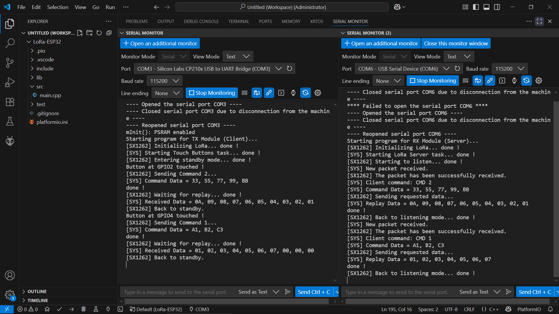
if you have a Raspberry Pi Pico RP2040 this code transmits OK
// RPi Pico RP2040_SX1262 _Transmit_Interrupt

// File>Examples>RadioLib>SX126x>SX126x_Transmit_Interrupt

// EDITs:
//  radio.begin frequency set to 868.0
//  transmitting byte array and printing it

/*
  RadioLib SX126x Transmit with Interrupts Example

  This example transmits LoRa packets with one second delays
  between them. Each packet contains up to 256 bytes
  of data, in the form of:
  - Arduino String
  - null-terminated char array (C-string)
  - arbitrary binary data (byte array)

  Other modules from SX126x family can also be used.

  For default module settings, see the wiki page
  https://github.com/jgromes/RadioLib/wiki/Default-configuration#sx126x---lora-modem

  For full API reference, see the GitHub Pages
  https://jgromes.github.io/RadioLib/
*/

// include the library
#include <RadioLib.h>

// RPi Pico RP2040
//MOSI: 19
//MISO: 16
//SCK: 18
//SS: 17
// NSS pin:   17
// DIO1 pin:  14
// NRST pin:  12
// BUSY pin:  13
SX1262 radio = new Module(17, 14, 12, 13);

// or detect the pinout automatically using RadioBoards
// https://github.com/radiolib-org/RadioBoards
/*
#define RADIO_BOARD_AUTO
#include <RadioBoards.h>
Radio radio = new RadioModule();
*/

// save transmission state between loops
int transmissionState = RADIOLIB_ERR_NONE;

// flag to indicate that a packet was sent
volatile bool transmittedFlag = false;

// this function is called when a complete packet
// is transmitted by the module
// IMPORTANT: this function MUST be 'void' type
//            and MUST NOT have any arguments!
#if defined(ESP8266) || defined(ESP32)
ICACHE_RAM_ATTR
#endif
void setFlag(void) {
  // we sent a packet, set the flag
  transmittedFlag = true;
}

void setup() {
  Serial.begin(115200);
  delay(2000);
  // initialize SX1262 with default settings
  Serial.print(F("\n\nRPi Pico RP2040 [SX1262] Initializing ... "));
  int state = radio.begin(868.0);
  if (state == RADIOLIB_ERR_NONE) {
    Serial.println(F("success!"));
  } else {
    Serial.print(F("failed, code "));
    Serial.println(state);
    while (true) { delay(10); }
  }

  // set the function that will be called
  // when packet transmission is finished
  radio.setPacketSentAction(setFlag);

  // start transmitting the first packet
  Serial.print(F("[SX1262] Sending first packet ... "));

  // you can transmit C-string or Arduino string up to
  // 256 characters long
  transmissionState = radio.startTransmit("Hello World!");

  // you can also transmit byte array up to 256 bytes long
  /*
    byte byteArr[] = {0x01, 0x23, 0x45, 0x67,
                      0x89, 0xAB, 0xCD, 0xEF};
    state = radio.startTransmit(byteArr, 8);
  */
}

// counter to keep track of transmitted packets
int count = 0;

void loop() {
  // check if the previous transmission finished
  if (transmittedFlag) {
    // reset flag
    transmittedFlag = false;

    if (transmissionState == RADIOLIB_ERR_NONE) {
      // packet was successfully sent
      Serial.println(F("transmission finished!"));

      // NOTE: when using interrupt-driven transmit method,
      //       it is not possible to automatically measure
      //       transmission data rate using getDataRate()

    } else {
      Serial.print(F("failed, code "));
      Serial.println(transmissionState);
    }

    // clean up after transmission is finished
    // this will ensure transmitter is disabled,
    // RF switch is powered down etc.
    radio.finishTransmit();

    // wait a second before transmitting again
    delay(1000);

    // send another one
    Serial.print(F("[SX1262] Sending another packet ... "));

    // you can transmit C-string or Arduino string up to
    // 256 characters long
    //String str = "Hello World! #" + String(count++);
    //transmissionState = radio.startTransmit(str);

    // you can also transmit byte array up to 256 bytes long
    static byte byteArr[] = { 0x01, 0x23, 0x45, 0x67,
                              0x89, 0xAB, 0xCD, 0xEF };
    for (int i = 0; i < sizeof(byteArr); i++)
      Serial.printf("%d ", byteArr[i]);
    transmissionState = radio.startTransmit(byteArr, 8);
    byteArr[0]++;
  }
}
RP2040 serial monitor output
RPi Pico RP2040 [SX1262] Initializing ... success!
[SX1262] Sending first packet ... transmission finished!
[SX1262] Sending another packet ... 1 35 69 103 137 171 205 239 transmission finished!
[SX1262] Sending another packet ... 2 35 69 103 137 171 205 239 transmission finished!
[SX1262] Sending another packet ... 3 35 69 103 137 171 205 239 transmission finished!
[SX1262] Sending another packet ... 4 35 69 103 137 171 205 239 transmission finished!
[SX1262] Sending another packet ... 5 35 69 103 137 171 205 239 transmission finished!
[SX1262] Sending another packet ... 6 35 69 103 137 171 205 239 transmission finished!
[SX1262] Sending another packet ... 7 35 69 103 137 171 205 239 transmission finished!
[SX1262] Sending another packet ... 8 35 69 103 137 171 205 239 transmission finished!
[SX1262] Sending another packet ... 9 35 69 103 137 171 205 239 transmission finished!
[SX1262] Sending another packet ... 10 35 69 103 137 171 205 239 transmission finished!
[SX1262] Sending another packet ... 11 35 69 103 137 171 205 239 transmission finished!
[SX1262] Sending another packet ... 12 35 69 103 137 171 205 239 transmission finished!
[SX1262] Sending another packet ... 13 35 69 103 137 171 205 239 transmission finished!
[SX1262] Sending another packet ... 14 35 69 103 137 171 205 239 transmission finished!
Heltec LoRa V2 receiver
Heltec LoRa V2  SX1276  [SX1276] Initializing ... success!
[SX1276] Starting to listen ... success!
[SX1276] Received packet!
[SX1276] Data:          3 35 69 103 137 171 205 239
[SX1276] RSSI:          -66.00 dBm
[SX1276] SNR:           9.50 dB
[SX1276] Frequency error:       -3839.89 Hz
[SX1276] Received packet!
[SX1276] Data:          4 35 69 103 137 171 205 239
[SX1276] RSSI:          -65.00 dBm
[SX1276] SNR:           11.25 dB
[SX1276] Frequency error:       -3835.69 Hz
[SX1276] Received packet!
[SX1276] Data:          5 35 69 103 137 171 205 239
[SX1276] RSSI:          -65.00 dBm
[SX1276] SNR:           10.00 dB
[SX1276] Frequency error:       -3835.69 Hz
[SX1276] Received packet!
[SX1276] Data:          6 35 69 103 137 171 205 239
[SX1276] RSSI:          -65.00 dBm
[SX1276] SNR:           11.00 dB
[SX1276] Frequency error:       -3848.27 Hz
[SX1276] Received packet!
[SX1276] Data:          7 35 69 103 137 171 205 239
[SX1276] RSSI:          -67.00 dBm
[SX1276] SNR:           12.75 dB
[SX1276] Frequency error:       -3856.66 Hz
[SX1276] Received packet!
[SX1276] Data:          8 35 69 103 137 171 205 239
[SX1276] RSSI:          -65.00 dBm
[SX1276] SNR:           5.50 dB
[SX1276] Frequency error:       -3785.36 Hz
[SX1276] Received packet!
[SX1276] Data:          9 35 69 103 137 171 205 239
[SX1276] RSSI:          -64.00 dBm
[SX1276] SNR:           10.25 dB
[SX1276] Frequency error:       -3869.25 Hz
[SX1276] Received packet!
[SX1276] Data:          10 35 69 103 137 171 205 239
[SX1276] RSSI:          -65.00 dBm
[SX1276] SNR:           10.50 dB
[SX1276] Frequency error:       -3873.44 Hz
[SX1276] Received packet!
[SX1276] Data:          11 35 69 103 137 171 205 239
[SX1276] RSSI:          -63.00 dBm
[SX1276] SNR:           9.50 dB
[SX1276] Frequency error:       -3881.83 Hz
[SX1276] Received packet!
[SX1276] Data:          12 35 69 103 137 171 205 239
[SX1276] RSSI:          -66.00 dBm
[SX1276] SNR:           11.50 dB
[SX1276] Frequency error:       -3881.83 Hz
[SX1276] Received packet!
[SX1276] Data:          13 35 69 103 137 171 205 239
[SX1276] RSSI:          -66.00 dBm
[SX1276] SNR:           13.00 dB
[SX1276] Frequency error:       -3886.02 Hz
[SX1276] Received packet!
[SX1276] Data:          14 35 69 103 137 171 205 239
[SX1276] RSSI:          -66.00 dBm
[SX1276] SNR:           13.00 dB
[SX1276] Frequency error:       -3898.61 Hz
[SX1276] Received packet!
[SX1276] Data:          15 35 69 103 137 171 205 239
[SX1276] RSSI:          -67.00 dBm
[SX1276] SNR:           13.75 dB
[SX1276] Frequency error:       -3902.80 Hz
[SX1276] Received packet!
[SX1276] Data:          16 35 69 103 137 171 205 239
[SX1276] RSSI:          -66.00 dBm
[SX1276] SNR:           13.00 dB
[SX1276] Frequency error:       -3902.80 Hz
[SX1276] Received packet!
[SX1276] Data:          17 35 69 103 137 171 205 239
[SX1276] RSSI:          -69.00 dBm
[SX1276] SNR:           12.50 dB
[SX1276] Frequency error:       -3902.80 Hz
rather than soldering connections direct to the SX1262 module (photo in post 18) I use (try a search on Ebay)
"ESP8266 breakout board adapter plate for ESP-07, ESP-08 and ESP-12"
remove the surface mount resistors and solder the SX1262 directly onto the pads
 After a month of hard working...