Communication between 2 LoRa SX1262 modules

Hi ! I am verry beginer in this stuff... I ordered 2 LoRa modules with SX1262 chip: https://www.waveshare.com/wiki/Core1262-868M. Until they arrive, I thought to start studying about them... I will use ESP32-DevKitC and RadioLib to control them. I want to make a peer-to-peer communication, not LoRaWAN.

For now, I have this problem...
This Waveshare module has a RF Switch for the antenna. The switch is controlled by two pins: RX_EN and TX_EN.
This is the module schematics: https://files.waveshare.com/upload/c/c1/coresx1262_sch.pdf
And here is the Datasheet of the RF Switch: https://files.waveshare.com/upload/c/c6/datasheet-rtc6603sp-richwave.pdf
I want to understand what logic levels do I need to provide at this pins for Reception and Emision.
Combining the schematics of the module with the truth table from the RF Switch datasheet, results the following logic:

RX_EN ... TX_EN ... OUT ... IN
.... L ........... H ........ ON ... OFF
.... H ........... L ........ OFF ....ON

But on the presentation site of the module (the first link above), they say:

RXEN, TXEN are RF single-pole switch (SPDT) pins, RXEN low level, TXE high level, SX1262 is in receiving mode, RXEN high level, TXEN low level, SX1262 is in transmitting mode.

Which is exactly the opposite compared to the datasheet logic ! So, one of these must be wrong ... Which one ? The datasheet schematic or the website documentation ?

Please post a clear picture here.

No it's not. Try better.

What does waveshare say about your discovery?

Check to see if that is mentioned in the module data sheet or user guide. If it isn't, that would indicate incomplete, poor quality documentation, and likely, a problematic product.

Does the seller provide a clear, step-by-step "getting started" guide that shows an example of how the product is used?

Since you describe yourself as a beginner, save yourself a huge amount of trouble by buying modules from reliable distributors who provide excellent documentation, usage examples that actually work, and product support. They want you to succeed!

1 Like

how have you connected the SX1262 modules to the ESP32-DevKitC ?

for controlling SX1262 LoRa devices I use the SX12XX-LoRa library

e.g. for the heltec wifi-lora-32-v3 I use the following SX1262_Settings.h file settings

// Heltec ESP32S3 LoRa (V3) SX1262 receiver 

/*******************************************************************************************************
  Programs for Arduino - Copyright of the author Stuart Robinson - 04/04/20

  This program is supplied as is, it is up to the user of the program to decide if the program is
  suitable for the intended purpose and free from errors.
*******************************************************************************************************/

//*******  Setup hardware pin definitions here ! ***************

//These are the pin definitions for one of my own boards, a ESP32 shield base with my BBF board shield on
//top. Be sure to change the definitions to match your own setup. Some pins such as DIO2, DIO3, BUZZER
//may not be in used by this sketch so they do not need to be connected and should be included and be 
//set to -1.

#define SCK 9                                  //SCK on SPI3
#define MISO 11                                 //MISO on SPI3 
#define MOSI 10                                 //MOSI on SPI3 

#define NSS 8                                   //select pin on LoRa device
#define NRESET 12                               //reset pin on LoRa device
#define RFBUSY 13                               //busy line

#define LED1 2                                  //on board LED, high for on
#define DIO1 14                                 //DIO1 pin on LoRa device, used for RX and TX done 

#define LORA_DEVICE DEVICE_SX1262               //we need to define the device we are using


//*******  Setup LoRa Parameters Here ! ***************

//LoRa Modem Parameters
const uint32_t Frequency = 866000000;           //frequency of transmissions in hertz
const uint32_t Offset = 0;                      //offset frequency for calibration purposes

const uint8_t Bandwidth = LORA_BW_125;          //LoRa bandwidth
const uint8_t SpreadingFactor = LORA_SF7;       //LoRa spreading factor
const uint8_t CodeRate = LORA_CR_4_5;           //LoRa coding rate
const uint8_t Optimisation = LDRO_AUTO;         //low data rate optimisation setting, normally set to auto

const int8_t TXpower = 10;                      //LoRa transmit power in dBm


const uint16_t packet_delay = 1000;             //mS delay between packets

#define RXBUFFER_SIZE 32                        //RX buffer size  

you would need to edit the file to match the pins used on your ESP32-DevKitC

the SX1262 uses 3.3V logic

EDIT: did you try example code from File>Examples>RadioLib>SX126x

post your code (using code tags < CODE >)

I want to talk only about this Waveshare module because I already bought it and I have to deal with it.

Sorry about the broken links. I don't know why they not working. You can access those pdf's from the Waveshare product presentation (the first link).

Here's what matters...

The module schematic:

The RF Switch:


And the Waveshare documentation that says the logic is exactly the opposite:
"RXEN, TXEN are RF single-pole switch (SPDT) pins, RXEN low level, TXE high level, SX1262 is in receiving mode, RXEN high level, TXEN low level, SX1262 is in transmitting mode."

Has anyone used this Waveshare module to tell me what the correct polarities of the RX_EN and TX_EN signals are?

Then maybe ask Waveshare ..................

Indeed, this is the default logic of the RadioLib too, and the logic that results from the schematic and RF Switch truth table, but the Waveshare documentation say that the antenna is connected at the receiver when the TX_EN is high and RX_EN low...

I think only someone who used this module can tell us what are the correct polarities ...

suggest you try example code from File>Examples>RadioLib>SX126x, e.g. SX126x_Transmit_Interrupt and SX126x_Receive_Interrupt

SX126x_Transmit_Interrupt works OK on a Heltec LoRa V3 SX1262 module

this version is transmitting bytes

// Heltec LoRa SX1262 transmit test

// File>Examples>RadioLib>SX126x/SX126x_Transmit_Interrupt

// EDITs:
//  radio.begin frequency set to 868.0
//  transmitting byte array and printing it

/*
  RadioLib SX126x Transmit with Interrupts Example

  This example transmits LoRa packets with one second delays
  between them. Each packet contains up to 256 bytes
  of data, in the form of:
  - Arduino String
  - null-terminated char array (C-string)
  - arbitrary binary data (byte array)

  Other modules from SX126x family can also be used.

  For default module settings, see the wiki page
  https://github.com/jgromes/RadioLib/wiki/Default-configuration#sx126x---lora-modem

  For full API reference, see the GitHub Pages
  https://jgromes.github.io/RadioLib/
*/

// include the library
#include <RadioLib.h>

// Heltec LoRa V3  SX1262 has the following connections:
// NSS pin:   8
// DIO1 pin:  14
// NRST pin:  12
// BUSY pin:  13
SX1262 radio = new Module(8, 14, 12, 13);

// or detect the pinout automatically using RadioBoards
// https://github.com/radiolib-org/RadioBoards
/*
#define RADIO_BOARD_AUTO
#include <RadioBoards.h>
Radio radio = new RadioModule();
*/

// save transmission state between loops
int transmissionState = RADIOLIB_ERR_NONE;

// flag to indicate that a packet was sent
volatile bool transmittedFlag = false;

// this function is called when a complete packet
// is transmitted by the module
// IMPORTANT: this function MUST be 'void' type
//            and MUST NOT have any arguments!
#if defined(ESP8266) || defined(ESP32)
ICACHE_RAM_ATTR
#endif
void setFlag(void) {
  // we sent a packet, set the flag
  transmittedFlag = true;
}

void setup() {
  Serial.begin(115200);
  delay(2000);
  // initialize SX1262 with default settings
  Serial.print(F("\n\nHeltec LoRa V3 [SX1262] Initializing ... "));
  int state = radio.begin(868.0);
  if (state == RADIOLIB_ERR_NONE) {
    Serial.println(F("success!"));
  } else {
    Serial.print(F("failed, code "));
    Serial.println(state);
    while (true) { delay(10); }
  }

  // set the function that will be called
  // when packet transmission is finished
  radio.setPacketSentAction(setFlag);

  // start transmitting the first packet
  Serial.print(F("[SX1262] Sending first packet ... "));

  // you can transmit C-string or Arduino string up to
  // 256 characters long
  transmissionState = radio.startTransmit("Hello World!");

  // you can also transmit byte array up to 256 bytes long
  /*
    byte byteArr[] = {0x01, 0x23, 0x45, 0x67,
                      0x89, 0xAB, 0xCD, 0xEF};
    state = radio.startTransmit(byteArr, 8);
  */
}

// counter to keep track of transmitted packets
int count = 0;

void loop() {
  // check if the previous transmission finished
  if (transmittedFlag) {
    // reset flag
    transmittedFlag = false;

    if (transmissionState == RADIOLIB_ERR_NONE) {
      // packet was successfully sent
      Serial.println(F("transmission finished!"));

      // NOTE: when using interrupt-driven transmit method,
      //       it is not possible to automatically measure
      //       transmission data rate using getDataRate()

    } else {
      Serial.print(F("failed, code "));
      Serial.println(transmissionState);
    }

    // clean up after transmission is finished
    // this will ensure transmitter is disabled,
    // RF switch is powered down etc.
    radio.finishTransmit();

    // wait a second before transmitting again
    delay(1000);

    // send another one
    Serial.print(F("[SX1262] Sending another packet ... "));

    // you can transmit C-string or Arduino string up to
    // 256 characters long
    //String str = "Hello World! #" + String(count++);
    //transmissionState = radio.startTransmit(str);

    // you can also transmit byte array up to 256 bytes long
    static byte byteArr[] = { 0x01, 0x23, 0x45, 0x67,
                              0x89, 0xAB, 0xCD, 0xEF };
    for (int i = 0; i < sizeof(byteArr); i++)
      Serial.printf("%d ", byteArr[i]);
    transmissionState = radio.startTransmit(byteArr, 8);
    byteArr[0]++;
  }
}

used a Heltec LoRa V2 SX1276 as a receiver

// Heltec LoRa V2  SX1276 receive test

// File>Examples>RadioLib>SX127X/SX127x_Receive_Interrupt

// EDITs: 
//  SX1278 changed to SX1276 
//  radio.begin frequency set to 868.0
//  receiving byte array and printing it

/*
  RadioLib SX127x Receive with Interrupts Example

  This example listens for LoRa transmissions and tries to
  receive them. Once a packet is received, an interrupt is
  triggered. To successfully receive data, the following
  settings have to be the same on both transmitter
  and receiver:
  - carrier frequency
  - bandwidth
  - spreading factor
  - coding rate
  - sync word

  Other modules from SX127x/RFM9x family can also be used.

  For default module settings, see the wiki page
  https://github.com/jgromes/RadioLib/wiki/Default-configuration#sx127xrfm9x---lora-modem

  For full API reference, see the GitHub Pages
  https://jgromes.github.io/RadioLib/
*/

// include the library
#include <RadioLib.h>

// Heltec LoRa V2 SX1276 has the following connections:
// NSS pin:   18
// DIO0 pin:  26
// RESET pin: 14
// DIO1 pin:  35
SX1276 radio = new Module(18, 26, 14, 35);

// or detect the pinout automatically using RadioBoards
// https://github.com/radiolib-org/RadioBoards
/*
#define RADIO_BOARD_AUTO
#include <RadioBoards.h>
Radio radio = new RadioModule();
*/

// flag to indicate that a packet was received
volatile bool receivedFlag = false;

// this function is called when a complete packet
// is received by the module
// IMPORTANT: this function MUST be 'void' type
//            and MUST NOT have any arguments!
#if defined(ESP8266) || defined(ESP32)
ICACHE_RAM_ATTR
#endif
void setFlag(void) {
  // we got a packet, set the flag
  receivedFlag = true;
}

void setup() {
  Serial.begin(115200);
  delay(2000);

  // initialize SX1276 with default settings
  Serial.print(F("Heltec LoRa V2  SX1276  [SX1276] Initializing ... "));
  int state = radio.begin(868.0);
  if (state == RADIOLIB_ERR_NONE) {
    Serial.println(F("success!"));
  } else {
    Serial.print(F("failed, code "));
    Serial.println(state);
    while (true) { delay(10); }
  }

  // set the function that will be called
  // when new packet is received
  radio.setPacketReceivedAction(setFlag);

  // start listening for LoRa packets
  Serial.print(F("[SX1276] Starting to listen ... "));
  state = radio.startReceive();
  if (state == RADIOLIB_ERR_NONE) {
    Serial.println(F("success!"));
  } else {
    Serial.print(F("failed, code "));
    Serial.println(state);
    while (true) { delay(10); }
  }

  // if needed, 'listen' mode can be disabled by calling
  // any of the following methods:
  //
  // radio.standby()
  // radio.sleep()
  // radio.transmit();
  // radio.receive();
  // radio.scanChannel();
}

void loop() {
  // check if the flag is set
  if (receivedFlag) {
    // reset flag
    receivedFlag = false;

    // you can read received data as an Arduino String
    //String str;
    //int state = radio.readData(str);

    // you can also read received data as byte array
    byte byteArr[8];
    int numBytes = radio.getPacketLength();
    int state = radio.readData(byteArr, numBytes);


    if (state == RADIOLIB_ERR_NONE) {
      // packet was successfully received
      Serial.println(F("[SX1276] Received packet!"));

      // print data of the packet
      Serial.print(F("[SX1276] Data:\t\t"));
      //Serial.println(str);
      for (int i = 0; i < numBytes; i++)
        Serial.printf("%d ", byteArr[i]);

      // print RSSI (Received Signal Strength Indicator)
      Serial.print(F("\n[SX1276] RSSI:\t\t"));
      Serial.print(radio.getRSSI());
      Serial.println(F(" dBm"));

      // print SNR (Signal-to-Noise Ratio)
      Serial.print(F("[SX1276] SNR:\t\t"));
      Serial.print(radio.getSNR());
      Serial.println(F(" dB"));

      // print frequency error
      Serial.print(F("[SX1276] Frequency error:\t"));
      Serial.print(radio.getFrequencyError());
      Serial.println(F(" Hz"));

    } else if (state == RADIOLIB_ERR_CRC_MISMATCH) {
      // packet was received, but is malformed
      Serial.println(F("[SX1276] CRC error!"));

    } else {
      // some other error occurred
      Serial.print(F("[SX1276] Failed, code "));
      Serial.println(state);
    }
  }
}

transmitter serial output

Heltec LoRa V3 [SX1262] Initializing ... success!
[SX1262] Sending first packet ... transmission finished!
[SX1262] Sending another packet ... 1 35 69 103 137 171 205 239 transmission finished!
[SX1262] Sending another packet ... 2 35 69 103 137 171 205 239 transmission finished!
[SX1262] Sending another packet ... 3 35 69 103 137 171 205 239 transmission finished!
[SX1262] Sending another packet ... 4 35 69 103 137 171 205 239 transmission finished!
[SX1262] Sending another packet ... 5 35 69 103 137 171 205 239 transmission finished!
[SX1262] Sending another packet ... 6 35 69 103 137 171 205 239 transmission finished!
[SX1262] Sending another packet ... 7 35 69 103 137 171 205 239 transmission finished!
[SX1262] Sending another packet ... 8 35 69 103 137 171 205 239 transmission finished!
[SX1262] Sending another packet ... 9 35 69 103 137 171 205 239 transmission finished!
[SX1262] Sending another packet ... 10 35 69 103 137 171 205 239 transmission finished!
[SX1262] Sending another packet ... 11 35 69 103 137 171 205 239 transmission finished!
[SX1262] Sending another packet ... 12 35 69 103 137 171 205 239 transmission finished

receiver serial output

Heltec LoRa V2  SX1276  [SX1276] Initializing ... success!
[SX1276] Starting to listen ... success!
[SX1276] Received packet!
[SX1276] Data:		3 35 69 103 137 171 205 239 
[SX1276] RSSI:		-50.00 dBm
[SX1276] SNR:		12.00 dB
[SX1276] Frequency error:	-2149.58 Hz
[SX1276] Received packet!
[SX1276] Data:		4 35 69 103 137 171 205 239 
[SX1276] RSSI:		-49.00 dBm
[SX1276] SNR:		10.00 dB
[SX1276] Frequency error:	-2153.78 Hz
[SX1276] Received packet!
[SX1276] Data:		5 35 69 103 137 171 205 239 
[SX1276] RSSI:		-50.00 dBm
[SX1276] SNR:		12.25 dB
[SX1276] Frequency error:	-2162.16 Hz
[SX1276] Received packet!
[SX1276] Data:		6 35 69 103 137 171 205 239 
[SX1276] RSSI:		-51.00 dBm
[SX1276] SNR:		9.50 dB
[SX1276] Frequency error:	-2170.55 Hz

I seem to remember I have another SX1262 based module somewhere - will see if I can find it

@horace I haven't tried anything yet, because I just ordered the modules and they are still on the road... :slight_smile:

Here, the problem is not about the SX126x or the used library, but the polarity of the signals that controls the antenna RF Switch, that is particular to Waveshare modules... The test on other modules is no relevant.

I think just by doing a reception test, when I get the modules, I can find out the mystery ...

@srnet I ask them, but it does't make sense what they say:

  1. The product introduction page is correct. RXEN low level + TXEN high level is the receiving mode, and RXEN high level + TXEN low level is the transmitting mode, which is consistent with the specifications of the SX1262 chip.

  2. The RTC6603SP data sheet is the truth table of an independent RF switch. In the actual module, reverse control may be performed through circuit design, so the opposite logic is normal.

  3. When using, just follow the product instructions. The signal adaptation has been completed inside the module, and there is no need to consider the original truth table of RTC6603SP.

They say that the logic of the RF Switch is reversed by the module circuit, but from the presented schematic does not result in reversed behavior...

I'd go along with that.

Adafruit go to long lengths to support their products, and like Arduino itself, personally I think users, now and again, should support the project by buying their products.

Of course, money comes into it, but how often do you hear "my Nano clone doesn't work"? The time wasted and the frustration really isn't worth it.

it's the old saying, buy cheap, buy twice.

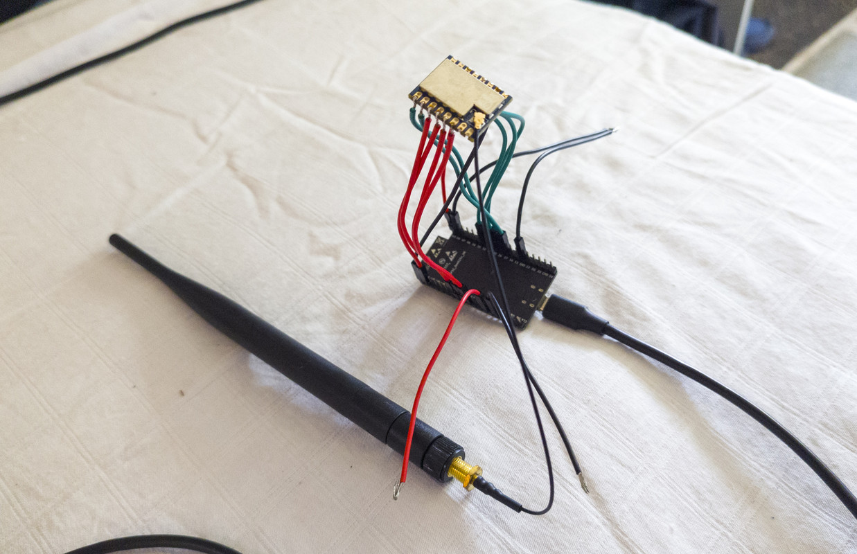
new test using a ESP32 with a Heltec_HT-RA62 SX1262 LoRa module
running File>Examples>RadioLib>SX126x/SX126x_Transmit_Interrupt

Transmitter code

// Heltec HT_62_SX1262 _Transmit_Interrupt

// File>Examples>RadioLib>SX126x/SX126x_Transmit_Interrupt

// EDITs:
//  radio.begin frequency set to 868.0
//  transmitting byte array and printing it

/*
  RadioLib SX126x Transmit with Interrupts Example

  This example transmits LoRa packets with one second delays
  between them. Each packet contains up to 256 bytes
  of data, in the form of:
  - Arduino String
  - null-terminated char array (C-string)
  - arbitrary binary data (byte array)

  Other modules from SX126x family can also be used.

  For default module settings, see the wiki page
  https://github.com/jgromes/RadioLib/wiki/Default-configuration#sx126x---lora-modem

  For full API reference, see the GitHub Pages
  https://jgromes.github.io/RadioLib/
*/

// include the library
#include <RadioLib.h>

// HT_62  SX1262 has the following connections:
// NSS pin:   5
// DIO1 pin:  14
// NRST pin:  12
// BUSY pin:  13
SX1262 radio = new Module(5, 14, 12, 13);

// or detect the pinout automatically using RadioBoards
// https://github.com/radiolib-org/RadioBoards
/*
#define RADIO_BOARD_AUTO
#include <RadioBoards.h>
Radio radio = new RadioModule();
*/

// save transmission state between loops
int transmissionState = RADIOLIB_ERR_NONE;

// flag to indicate that a packet was sent
volatile bool transmittedFlag = false;

// this function is called when a complete packet
// is transmitted by the module
// IMPORTANT: this function MUST be 'void' type
//            and MUST NOT have any arguments!
#if defined(ESP8266) || defined(ESP32)
ICACHE_RAM_ATTR
#endif
void setFlag(void) {
  // we sent a packet, set the flag
  transmittedFlag = true;
}

void setup() {
  Serial.begin(115200);
  delay(2000);
  // initialize SX1262 with default settings
  Serial.print(F("\n\nHT_62 [SX1262] Initializing ... "));
  int state = radio.begin(868.0);
  if (state == RADIOLIB_ERR_NONE) {
    Serial.println(F("success!"));
  } else {
    Serial.print(F("failed, code "));
    Serial.println(state);
    while (true) { delay(10); }
  }

  // set the function that will be called
  // when packet transmission is finished
  radio.setPacketSentAction(setFlag);

  // start transmitting the first packet
  Serial.print(F("[SX1262] Sending first packet ... "));

  // you can transmit C-string or Arduino string up to
  // 256 characters long
  transmissionState = radio.startTransmit("Hello World!");

  // you can also transmit byte array up to 256 bytes long
  /*
    byte byteArr[] = {0x01, 0x23, 0x45, 0x67,
                      0x89, 0xAB, 0xCD, 0xEF};
    state = radio.startTransmit(byteArr, 8);
  */
}

// counter to keep track of transmitted packets
int count = 0;

void loop() {
  // check if the previous transmission finished
  if (transmittedFlag) {
    // reset flag
    transmittedFlag = false;

    if (transmissionState == RADIOLIB_ERR_NONE) {
      // packet was successfully sent
      Serial.println(F("transmission finished!"));

      // NOTE: when using interrupt-driven transmit method,
      //       it is not possible to automatically measure
      //       transmission data rate using getDataRate()

    } else {
      Serial.print(F("failed, code "));
      Serial.println(transmissionState);
    }

    // clean up after transmission is finished
    // this will ensure transmitter is disabled,
    // RF switch is powered down etc.
    radio.finishTransmit();

    // wait a second before transmitting again
    delay(1000);

    // send another one
    Serial.print(F("[SX1262] Sending another packet ... "));

    // you can transmit C-string or Arduino string up to
    // 256 characters long
    //String str = "Hello World! #" + String(count++);
    //transmissionState = radio.startTransmit(str);

    // you can also transmit byte array up to 256 bytes long
    static byte byteArr[] = { 0x01, 0x23, 0x45, 0x67,
                              0x89, 0xAB, 0xCD, 0xEF };
    for (int i = 0; i < sizeof(byteArr); i++)
      Serial.printf("%d ", byteArr[i]);
    transmissionState = radio.startTransmit(byteArr, 8);
    byteArr[0]++;
  }
}

using a Heltec LoRa V2 SX1276 as a receiver as in post 10

Heltec_HT-RA62 SX1262 LoRa module serial monitor output

HT_62 [SX1262] Initializing ... success!
[SX1262] Sending first packet ... transmission finished!
[SX1262] Sending another packet ... 1 35 69 103 137 171 205 239 transmission finished!
[SX1262] Sending another packet ... 2 35 69 103 137 171 205 239 transmission finished!
[SX1262] Sending another packet ... 3 35 69 103 137 171 205 239 transmission finished!
[SX1262] Sending another packet ... 4 35 69 103 137 171 205 239 transmission finished!
[SX1262] Sending another packet ... 5 35 69 103 137 171 205 239 transmission finished!
[SX1262] Sending another packet ... 6 35 69 103 137 171 205 239 transmission finished!
[SX1262] Sending another packet ... 7 35 69 103 137 171 205 239 transmission finished!
[SX1262] Sending another packet ... 8 35 69 103 137 171 205 239 transmission finished!
[SX1262] Sending another packet ... 9 35 69 103 137 171 205 239 transmission finished!
[SX1262] Sending another packet ... 10 35 69 103 137 171 205 239 transmission finished!
[SX1262] Sending another packet ... 11 35 69 103 137 171 205 239 transmission finished!
[SX1262] Sending another packet ... 12 35 69 103 137 171 205 239 transmission finished!
[SX1262] Sending another packet ... 13 35 69 103 137 171 205 239 transmission finished!
[SX1262] Sending another packet ... 14 35 69 103 137 171 205 239 transmission finished!
[SX1262] Sending another packet ... 15 35 69 103 137 171 205 239 transmission finished!
[SX1262] Sending another packet ... 16 35 69 103 137 171 205 239 transmission finished!
[SX1262] Sending another packet ... 17 35 69 103 137 171 205 239 transmission finished!
[SX1262] Sending another packet ... 18 35 69 103 137 171 205 239 transmission finished!
[SX1262] Sending another packet ... 19 35 69 103 137 171 205 239 transmission finished!

Heltec LoRa V2 SX1276 as a receiver serial monitor output

Heltec LoRa V2  SX1276  [SX1276] Initializing ... success!
[SX1276] Starting to listen ... success!
[SX1276] Received packet!
[SX1276] Data:		3 35 69 103 137 171 205 239 
[SX1276] RSSI:		-50.00 dBm
[SX1276] SNR:		10.00 dB
[SX1276] Frequency error:	-3961.52 Hz
[SX1276] Received packet!
[SX1276] Data:		4 35 69 103 137 171 205 239 
[SX1276] RSSI:		-50.00 dBm
[SX1276] SNR:		9.00 dB
[SX1276] Frequency error:	-3969.91 Hz
[SX1276] Received packet!
[SX1276] Data:		5 35 69 103 137 171 205 239 
[SX1276] RSSI:		-49.00 dBm
[SX1276] SNR:		9.75 dB
[SX1276] Frequency error:	-3978.30 Hz
[SX1276] Received packet!
[SX1276] Data:		6 35 69 103 137 171 205 239 
[SX1276] RSSI:		-50.00 dBm
[SX1276] SNR:		9.75 dB
[SX1276] Frequency error:	-3986.69 Hz
[SX1276] Received packet!
[SX1276] Data:		7 35 69 103 137 171 205 239 
[SX1276] RSSI:		-50.00 dBm
[SX1276] SNR:		9.50 dB
[SX1276] Frequency error:	-3995.07 Hz
[SX1276] Received packet!
[SX1276] Data:		8 35 69 103 137 171 205 239 
[SX1276] RSSI:		-50.00 dBm
[SX1276] SNR:		9.75 dB
[SX1276] Frequency error:	-3999.27 Hz
[SX1276] Received packet!
[SX1276] Data:		9 35 69 103 137 171 205 239 
[SX1276] RSSI:		-50.00 dBm
[SX1276] SNR:		9.75 dB
[SX1276] Frequency error:	-4003.46 Hz

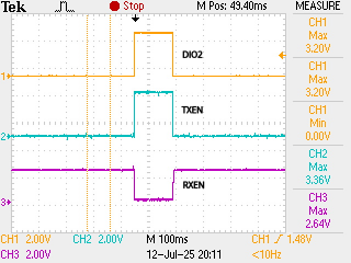
looking at the Heltec_HT-RA62 SX1262 LoRa schematic DIO2 is connected via some circuitry to TXEN and RXEN
when transmitting oscilloscope shows DIO2 controlling TXEN (going HIGH) and RXEN (going LOW)

the schematic of the Waveshare Core1262-868M in post 7 does not show TXEN and RXEN connected to anything

suggest you try the File>Examples>RadioLib>SX126x/SX126x_Transmit_Interrupt and SX126x_Receive_Interrupt
assuming you connected them correctly you should get a initialization success message, e.g. transmitter

[SX1262] Initializing ... success!
[SX1262] Sending first packet ... transmission finished!
[SX1262] Sending another packet ... 1 35 69 103 137 171 205 239 transmission finished!
[SX1262] Sending another packet ... 2 35 69 103 137 171 205 239 transmission finished!

if it fails you have a wiring problem

if you get initialization success messages on transmiter and receiver the transmitter should show it is transmitting messages and the receiver should show received messages

if the receiver does not show received messages check the transmitter TXEN and RXEN lines with an oscilloscope if possible

as the schematic of the Waveshare Core1262-868M in post 7 does not show TXEN and RXEN connected to anything you may have to control them yourself, e.g. on transmit taking TXEN HIGH and RXEN LOW

1 Like

Thanks for the test, @horace !
Indeed, on my module, RX_EN, and TX_EN are not connected anywhere internaly. The user must command those pins. Fortunately, RadioLib can control those pins automatically. All I have to do is to tell it which are those pins and what polarity should it use. I will try with the polarity that is shown on your oscilloscope, first...

did you get the Waveshare Core1262-868M communication working?

Not yet. I still wait for the modules to arrive from AliExpress. I think in a few days I will have them. In the meantime, I'm working on the software for them and studying the RadioLib library... I'll let you know as soon as I test them.

I received the LoRa modules and wire on of them to a ESP32.


The program I made for it is here:
https://github.com/MarusGradinaru/lora-p2p/blob/main/lora_client_server_example.cpp

The software is the same for both the Client module and the Server module, and the version is chosen during compilation through the "#define TX_MODULE" directive. I implemented 2 test commands: CMD1 and CMD2, which send the command along with a small data buffer, and receive another buffer with the requested data back... The commands are sent when touching the GPIO4 and GPIO2 pins of the ESP32-DevKitC.

I uploaded the RX version to the ESP32 and everything was ok, no errors:

rst:0x1 (POWERON_RESET),boot:0x13 (SPI_FAST_FLASH_BOOT)
configsip: 0, SPIWP:0xee
clk_drv:0x00,q_drv:0x00,d_drv:0x00,cs0_drv:0x00,hd_drv:0x00,wp_drv:0x00
mode:DIO, clock div:1
load:0x3fff0030,len:1344
load:0x40078000,len:13964
load:0x40080400,len:3600
entry 0x400805f0
[   464][I][esp32-hal-psram.c:96] psramInit(): PSRAM enabled
Starting program for RX Module (Server)... 
[SX1262] Initializing LoRa... done !
[SYS] Starting LoRa Server task... done !
[SX1262] Starting to listen... done !

But the problem is that I don't have a second ESP32 module to control the TX version of LoRa... and the software I wrote is not compatible with Raspberry Pi Pico, which I have one, because it use FreeRTOS tasks... So, I need to write another version for Pico.

Is there a way to check if the reception works without having a TX module to transmit something ?

No.

Its a LoRa receiver so something needs to transmit a LoRa signal with the same LoRa settings used by the receiver.

you need a second 3.3V logic microcontroller - ESP32, RP21040, STM32, etc

from the serial monitor messages in post 18 looks as though the ESP32 <> SZ1262 communication is working OK

Yes, but I don't think that the SX1262 module knows if it has an antenna attached, or not... 'Cause this is what I want to find out, if the RF switch works correctly...