Comunication pins for MAX31865

Hello !

I am trying to do a PT100 temperature sensor and MAX31865 board project with Arduino, the code and wiring are working perfectly.

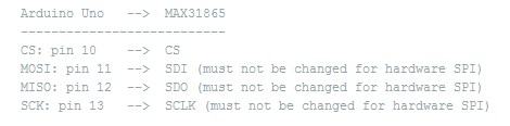
The thing is, I want to add more than one PT100 and boards to this projects (I need to have 8 sensors) but the communication pins are predefined in the library and I don´t know how to change them:

pin 11:MOSI-SDI
pin 12: MISO-SDO
pin 13: SCK-SCLK

If these pins were modifiable I could defined more sensors, right? I mean, 3 of them for each sensor.

Eventhough I have tried to modify the library, I can´t even tell where they are predefined.

This is te library:

In the images attached you can see that the sensor is working on the serial and the communication pins i mean.

Thank you for your help.
Anyone has done a similar porject with several sensors and a MAX31865 board?

conexión pines(1).jpg

The board has SPI bus interface. All boards would share the SCK, MOSI and MISO pins (SPI bus). Each board needs to have a separate chip (slave) select (CS) pin. In code the CS pin is set to active for the board that you want to read.

groundfungus:
The board has SPI bus interface. All boards would share the SCK, MOSI and MISO pins (SPI bus). Each board needs to have a separate chip (slave) select (CS) pin. In code the CS pin is set to active for the board that you want to read.

I get it, thank you.

I have done the wiring for 2 sensors but I don´t know how to do the code for both sensors,

what should I do to print on the serial both temperatures?

Here is the code i am using:

#include <SPI.h>
#include <MAX31865.h>

#define RTD_CS_PIN1 53

// For PT 1000 (Ref on breakout board = 3900 Ohms 0.1%)
MAX31865_RTD rtd( MAX31865_RTD::RTD_PT1000, RTD_CS_PIN1, 3875 );

void setup()
{
Serial.begin( 115200 );

/* Initialize SPI communication. */
SPI.begin( );
SPI.setClockDivider( SPI_CLOCK_DIV16 );
SPI.setDataMode( SPI_MODE3 );

/* Allow the MAX31865 to warm up. */
delay( 100 );

/* Configure:

V_BIAS enabled
Auto-conversion
1-shot disabled
3-wire enabled
Fault detection: automatic delay
Fault status: auto-clear
50 Hz filter
Low threshold: 0x0000
High threshold: 0x7fff
*/
rtd.configure( true, true, false, false, MAX31865_FAULT_DETECTION_NONE,
true, true, 0x0000, 0x7fff );
}

void loop()
{
rtd.read_all( );

if( rtd.status( ) == 0 )
{
** double temperature = rtd.temperature( );**
** Serial.print( " T = ");**
** Serial.print( temperature, 1 );**
** Serial.println(" deg C" );**
}
else
{
Serial.print( "RTD fault register: " );
Serial.print( rtd.status( ) );
Serial.print( ": " );
if( rtd.status( ) & MAX31865_FAULT_HIGH_THRESHOLD )
{
Serial.println( "RTD high threshold exceeded" );
}
else if( rtd.status( ) & MAX31865_FAULT_LOW_THRESHOLD )
{
Serial.println( "RTD low threshold exceeded" );
}
else if( rtd.status( ) & MAX31865_FAULT_REFIN )
{
Serial.println( "REFIN- > 0.85 x V_BIAS" );
}
else if( rtd.status( ) & MAX31865_FAULT_REFIN_FORCE )
{
Serial.println( "REFIN- < 0.85 x V_BIAS, FORCE- open" );
}
else if( rtd.status( ) & MAX31865_FAULT_RTDIN_FORCE )
{
Serial.println( "RTDIN- < 0.85 x V_BIAS, FORCE- open" );
}
else if( rtd.status( ) & MAX31865_FAULT_VOLTAGE )
{
Serial.println( "Overvoltage/undervoltage fault");
}
else
{
Serial.println( "Unknown fault; check connection" );
}
}

delay( 1000 );
}

50e5d529ce395f2f7a000000.png

Please use code tags when you post code. All that scrolling makes me tired.

#define RTD_CS_PIN1    53

Here is where you tell the sketch which pin are to be used as chip selects for the individual boards. You need a pin for each board. So:

#define RTD_CS_PIN2  54  // or pin of your choice

For the second board

MAX31865_RTD rtd( MAX31865_RTD::RTD_PT1000, RTD_CS_PIN1, 3875 );
MAX31865_RTD rtd2( MAX31865_RTD::RTD_PT1000, RTD_CS_PIN2, 3875 );

This where you create an instance and assign some constants. Configure a different RTD_CS_PIN for each instance. I made the second instance separate for readablity and changed the CS pin.

rtd.configure( true, true, false, false, MAX31865_FAULT_DETECTION_NONE,
                 true, true, 0x0000, 0x7fff );

This configures an instance of an rtd. You will need a configuration for each instance.

rtd2.configure( true, true, false, false, MAX31865_FAULT_DETECTION_NONE,
                 true, true, 0x0000, 0x7fff );

I will leave it to you to find out what all those parameters mean.

So now you have 2 instances created and configured rtd (CS=53) and rtd2 (CS=54).

rtd.read_all( );
rtd2.read_all( );

I cant test this but hope it helps.