Conditional ground pin?

Hello, I am playing with an Arduino Nano and a seven-segment display. The display has ten terminals, and by simple trial-and-error it appears two of them are a common ground and the remaining eight connect each to one of the illuminated segments.

I've figured out which voltage input goes to each segment, and created a simple test that draws ten digits in sequence. That works, but it uses nine pins of the Arduino.

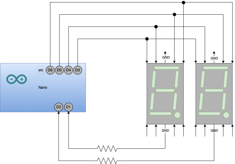
What I am thinking now is, to add a second digit. Maybe to make a speedometer heads-up display in the future.

I have recently read about the digital input pullup resistor mode... and that's got me thinking: is there a way I could blast both displays with the same input, but conditionally choose one or the other by allowing the ground connection or not? A "conditional ground" mode of the arduino pin, that would allow some current to run into it to ground?

I am guessing I could do this with two transistors... but I do not have any transistor. I thought it would be cool to learn and use a built-in Arduino feature if it exists.

Video of the single digit working with my code


int pin                 = 5;     //      D7 D7 D7
const int MIDDLE        = pin++; //    D6         D8
const int TOP_LEFT      = pin++; //    D6         D8
const int TOP           = pin++; //    D6         D8
const int TOP_RIGHT     = pin++; //       D5 D5 D5
const int BOTTOM_LEFT   = pin++; //    D9         D11
const int BOTTOM        = pin++; //    D9         D11
const int BOTTOM_RIGHT  = pin++; //    D9         D11
const int DOT           = pin++; //     D10 D10 D10    D12


void setup() {
  int pin = MIDDLE;
  pinMode( pin++, OUTPUT );
  pinMode( pin++, OUTPUT );
  pinMode( pin++, OUTPUT );
  pinMode( pin++, OUTPUT );
  pinMode( pin++, OUTPUT );
  pinMode( pin++, OUTPUT );
  pinMode( pin++, OUTPUT );
  pinMode( pin++, OUTPUT );
}

void loop() {
  blank();
  long seconds = 1000 * 1; // seconds
  delay( seconds );
  draw1();
  delay( seconds );
  draw2();
  delay( seconds );
  draw3();
  delay( seconds );
  draw4();
  delay( seconds );
  draw5();
  delay( seconds );
  draw6();
  delay( seconds );
  draw7();
  delay( seconds );
  draw8();
  delay( seconds );
  draw9();
  delay( seconds );
  draw0();
  delay( seconds );
  
}

// illuminate each segment in turn
void test() {
  long seconds = 1000 * 1; // seconds
  pin = MIDDLE;
  digitalWrite( pin, HIGH ); delay( seconds );
  digitalWrite( ++pin, HIGH ); delay( seconds );
  digitalWrite( ++pin, HIGH ); delay( seconds );
  digitalWrite( ++pin, HIGH ); delay( seconds );
  digitalWrite( ++pin, HIGH ); delay( seconds );
  digitalWrite( ++pin, HIGH ); delay( seconds );
  digitalWrite( ++pin, HIGH ); delay( seconds );
  digitalWrite( ++pin, HIGH );  
}

void blank() {
  pin = MIDDLE;
  digitalWrite( pin, LOW );
  digitalWrite( ++pin, LOW );
  digitalWrite( ++pin, LOW );
  digitalWrite( ++pin, LOW );
  digitalWrite( ++pin, LOW );
  digitalWrite( ++pin, LOW );
  digitalWrite( ++pin, LOW );
  digitalWrite( ++pin, LOW );
}

void draw0() {
  blank();
  digitalWrite( TOP_LEFT, HIGH );
  digitalWrite( TOP, HIGH );
  digitalWrite( TOP_RIGHT, HIGH );
  digitalWrite( BOTTOM_RIGHT, HIGH );
  digitalWrite( BOTTOM, HIGH );
  digitalWrite( BOTTOM_LEFT, HIGH );
}

void draw1() {
  blank();
  digitalWrite( TOP_RIGHT, HIGH );
  digitalWrite( BOTTOM_RIGHT, HIGH );
}

void draw2() {
  blank();
  digitalWrite( TOP, HIGH );
  digitalWrite( TOP_RIGHT, HIGH );
  digitalWrite( MIDDLE, HIGH );
  digitalWrite( BOTTOM_LEFT, HIGH );
  digitalWrite( BOTTOM, HIGH );
}

void draw3() {
  blank();
  digitalWrite( TOP, HIGH );
  digitalWrite( TOP_RIGHT, HIGH );
  digitalWrite( MIDDLE, HIGH );
  digitalWrite( BOTTOM_RIGHT, HIGH );
  digitalWrite( BOTTOM, HIGH );
}

void draw4() {
  blank();
  digitalWrite( TOP_LEFT, HIGH );
  digitalWrite( MIDDLE, HIGH );
  digitalWrite( TOP_RIGHT, HIGH );
  digitalWrite( BOTTOM_RIGHT, HIGH );
}

void draw5() {
  blank();
  digitalWrite( TOP, HIGH );
  digitalWrite( TOP_LEFT, HIGH );
  digitalWrite( MIDDLE, HIGH );
  digitalWrite( BOTTOM_RIGHT, HIGH );
  digitalWrite( BOTTOM, HIGH );
}

void draw6() {
  blank();
  digitalWrite( TOP, HIGH );
  digitalWrite( TOP_LEFT, HIGH );
  digitalWrite( BOTTOM_LEFT, HIGH );
  digitalWrite( BOTTOM, HIGH );
  digitalWrite( BOTTOM_RIGHT, HIGH );
  digitalWrite( MIDDLE, HIGH );
}

void draw7() {
  blank();
  digitalWrite( TOP, HIGH );
  digitalWrite( TOP_RIGHT, HIGH );
  digitalWrite( BOTTOM_RIGHT, HIGH );
}

void draw8() {
  blank();
  digitalWrite( TOP_LEFT, HIGH );
  digitalWrite( TOP, HIGH );
  digitalWrite( TOP_RIGHT, HIGH );
  digitalWrite( MIDDLE, HIGH );
  digitalWrite( BOTTOM_RIGHT, HIGH );
  digitalWrite( BOTTOM, HIGH );
  digitalWrite( BOTTOM_LEFT, HIGH );
}

void draw9() {
  blank();
  digitalWrite( MIDDLE, HIGH );
  digitalWrite( TOP_LEFT, HIGH );
  digitalWrite( TOP, HIGH );
  digitalWrite( TOP_RIGHT, HIGH );
  digitalWrite( BOTTOM_RIGHT, HIGH );
  digitalWrite( BOTTOM, HIGH ); // curly
}

I'm sorry to have to tell you that you haven't invented anything new with your idea. This is exactly how these displays are intended to be used.

The technique is called display multiplexing.

That's exactly what pinMode(pin, OUTPUT); plus digitalWrite(pin, LOW) achieves.

1 Like

Aha, fantastic! Thank you. It's weirdly comforting to know I can do this myself from scratch and not have to buy an interface or use a library.

Do you happen to know how many mA I can drive through that poor terminal on the Arduino Nano? For the time being I just randomly chose some resistors but I will have to calculate now.

About 25~30mA.

40mA is absolute max but you want to stay under 80% of that to give your Nano a long life.

1 Like

Thank you very much!

You should consider using a separate resistor for each LED segment in order that the current remains consistent whether say 2 segments are lit when displaying a 1 or 7 are lit when displaying an 8

1 Like

Only one resistor for each digit is necessary. But to avoid the problem @UKHeliBob mentioned, you need to multiplex the displays segment-by-segment, not digit-by-digit.

Oh... I hadn't thought of that. Thank you.

I saw some similar work https://www.youtube.com/watch?v=7ybz4yCNgcQ and was wondering why the builder wasted so much money on all those resistors. I tried to learn something more from that video, but counting the little yellow wires made my eyes go funny.

I do not follow. I'm trying to visualise this - I think I would still need eight resistors, one per segment. Is there a diagram you could point me to?

I should point out that these figures are for classic Nano, Uno, Mega and others based on AVR microcontroller chips.

Several other models which, confusingly, also bear the "Nano" name, like Nano 33, and Arduino based on other microcontroller chips, may have different limits, sometimes much lower.

1 Like

Yeah, check out post #1 above!

When you multiplex segment by segment, only one segment per digit is lit at any instant, so only one resistor per digit needed.

That is one of my old videos.

I was trying out a relatively unusual technique called Charlieplexing. It's interesting, but for now, suggest you focus on regular multiplexing.

1 Like

When doing that remember these points:

  • LEDs don't need 20mA or 30mA in order to light. If there is sufficient voltage, they will light. With less current they will be dimmer, but they could still be bright enough.
  • Consider how many segments, that may be lit at the same instant, will be connected to any Arduino pin. If more than one, you will need a resistor per segment, and the value of those resistors needs to keep the total current, flowing into or out of any pin, below that 25~30mA limit.

I didn't redesign the resistors yet, but I did get a second digit to work in a simulator.
I'm surprised that it is so sensitive to the timing of me clearing out the segments and switching the ground circuits. If I switch the order of clear() and selectDigit() functions, there are effects left that corrupt the figures in the display. Is this digitalWrite technique slow, and is there a better switching approach, like using ports or something?

Each digitalWrite() takes about 15us if I remember. That's 67,000 per second, so I don't think that's the problem. Or at least not the problem on a real Nano. You are running it on a simulator, so don't know how accurately it reflects reality.

The quickest and cleanest way to swap between digits will be to turn the previous digit off by removing it's "conditional ground" as you put it, then setting up the segments for the next digit, then switching on the ground for the next digit.

You can reduce the number of digitalWrites() getting executed by removing your blank() function and having your number setup functions always set all 8 segments. You are calling blank() twice unnecessarily anyway.

1 Like

Just to show how unrepresentative of reality this simulator is, both digits of your display seem to work even though the resistor for one of them is 220R and the resistor for the other digit is 220K which is 1000 times higher. In reality you probably wouldn't be able to see that digit light at all.

Clearly the simulator also won't reflect the problem @UKHeliBob told you about either.

Well, the simulator is all I have, because the second display isn't arriving until tomorrow.

In the meanwhile, I refactored a couple times and now I have multiplexing working by segment. Many thanks to @PaulRB and @UKHeliBob for your guidance.

332 lines of code to multiplex a 2 digit 7 segment display. That may be a new record, even without using any library. If you would like some hints how to dramatically simplify and shorten the code, just ask.

Each digit could be driven by an 8 bit shift register with resistor per bit, might need a transistor each to get even brightness always.

There are led driver chips with 16 outputs and plenty of output per pin... at higher cost. They could drive 2 digits each.

This topic was automatically closed 180 days after the last reply. New replies are no longer allowed.