I input 12V DC and the output was 12V instead of 3.3V. I double checked the soldering, the cut...etc. I did the same thing with 2 other modules but they all showed the same results. Any advice is greatly appreciated.
Use a razor knife like X-Acto and doing as little other damage as possible cut the very thin trace at the top of the selector area to disconnect the potentiometer.
Maybe google
cutting a PCB trace
You can also alternate use a small drill bit and carefully drill a pit in the middle of that trace. Obvsly do not go deep or through the board.
Next, jumper the two small pads with just enough solder to do that.
Usually we want to avoid solder bridges, and practice to avoid making them. Here we want to, so if you have any other scraps of PCB board see how much time and solder it takes to leave behind just the right amount.
Your first attempt had too much solder on the pads, it looks like it spilled over to the large ground plane area. You want only the two tinned pads.
Later, you can clean up the board you mangled. With luck, it will have survived. For that, SolderWick will be your friend.
Now the output shows 3.3V. I find that this module is difficult to deal with (at least for me). To make a "delicate" cut and solder was not easy at all. Thank you all for your help.
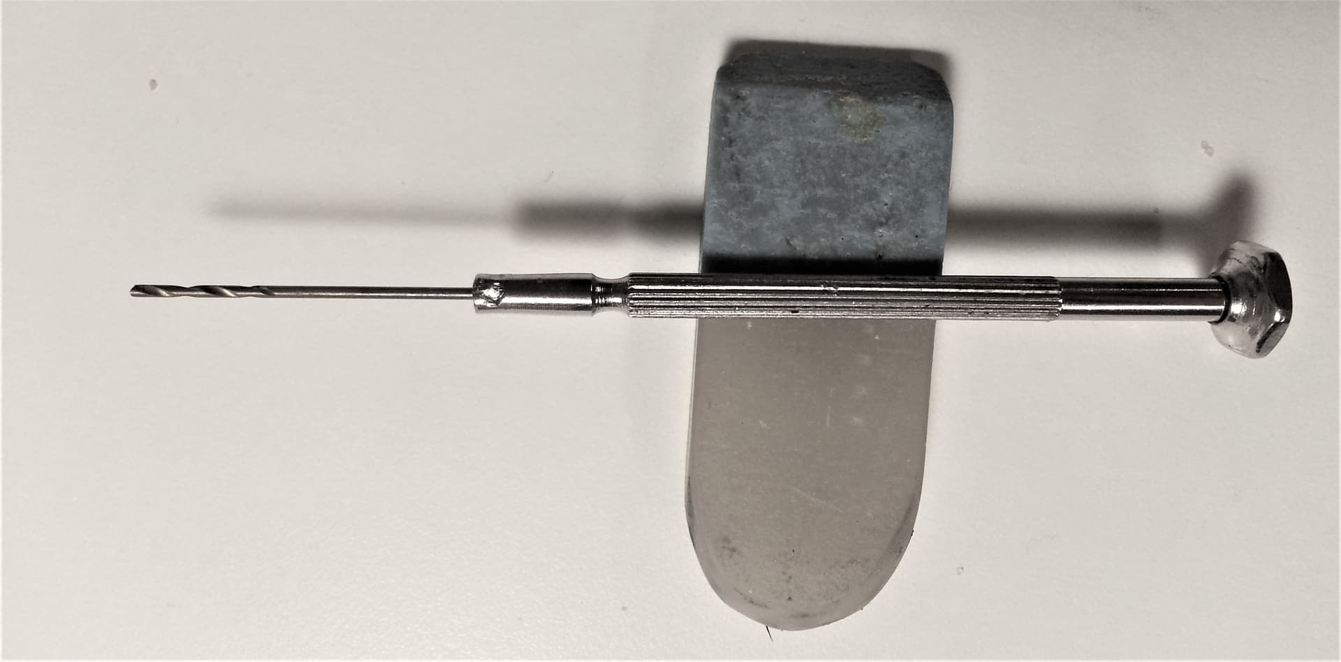
For cutting tracks on a PCB I use the point of a modelling knife spun around to make a tiny perforation in the copper track then use a 1mm twist drill mounted in the shaft of a (broken) jewellers' screwdriver to cut the through the width of the track. If necessary, then a larger drill in a hand held chuck to finish it off.