I have this motor, JGA25-371-12v-201rpm:
https://www.openimpulse.com/blog/products-page/25d-gearmotors/jga25-371-dc-gearmotor-encoder-201-rpm-12-v-2/
The encoder at the bottom looks like the attached photo. The six wires from top to bottom are:
color label
white ---M2
blue ----3.3v
green---C2
yellow--C1
black---gnd
red-----M1
I am confused about the 3.3v since the motor is labeled as a 12v motor.
I am guessing the C1 and C2 are the encoder outputs?
I am guessing M1 and M2 are 12v?
I was going to hook this up to an arduino motor shield:
since it needs its own 12v. but how do i hook up all the other wires? Is there a code example I can play with to figure it out?


The data signal level is 3.3 V. The encoder provides a steady 3.3 V probably for reference. If your microcontroller is very picky and say needs 5V for data, use a level shifter. This level shifter needs the 3.3 V reference, as well as a 5 V reference from your controller.
Hi,
The Blue and Black wires need a 3.3V supply.
This is to power the encoder, possibly a quadrature encoder in the back of the motor.
The two outputs Yellow and Green supply a 3.3V pulsed output.
The encoder does not need to be powered up for the motor to work,
The encoder is if you want to regulate the speed of the motor to within tight limits.
Tom... 
Aha, that makes more sense than my explanation.
thank you for your replies. but I am still a little unclear. TomGeorge, you said the the blue AND black wires need 3.3v. I assume you meant that a 3.3 v power supply is needed and its positive goes to blue and its negative goes to black. Is it advisable to use the arduino for this power source? I guess the level shifter would be attached to the arduino which puts out 5v and the shifter's output would go to the blue and black wires.
To regulate the speed of the motor, I need to modulate the 12v power. How can an arduino do that? Do I need a transistor or something between the arduino and the motor? Since the arduino outputs high or low (5v or nothing) then I guess another board is needed to translate this digital signal to an analog voltage. This intermediary board obviously has to be able to handle the current requirements of the motor. Can you suggest a board for this purpose? I was thinking of the Adafruit v2 motor shield.
Finally, the encoder outputs must be 3.3v yes? can I connect these directly to an arduino and read them? or are those voltages too low and requiring yet another voltage shifter?
Hook up your motor with the shield you mentioned in your first post. Provide that shield with the 12 V from your power source. Provide your Arduino with 5 V. Your Arduino has a 3.3 V output, which I believe is sufficient for your motor encoder.
You don't use level shifters to provide 12 V for a motor from Arduino's 5 V output! The 12 V for the motor is not for the encoder, only for motion, which needs lots of current.
The motor shield should take care of regulating the speed of the motor. You write "analogue" values to the dedicated pins, which will output the PWM signal, which the motor shield outputs as the driving power to the motor.
Where did this 3.3V spec come from? Most of those encoders have a 3.3 to 20V input range. Just use 5v.
See the Pololu site.
The motor shield mentioned(I have one) has a dedicated chip to produce the pwm. It uses only I2C for communicating. The shield is stackable by assigning different addresses for the I2C.
skypickle:
I have this motor, JGA25-371-12v-201rpm:
JGA25-371 DC Gearmotor with Encoder (201 RPM at 12 V) | Open ImpulseOpen Impulse
The encoder at the bottom looks like the attached photo. The six wires from top to bottom are:
color label
white ---M2
blue ----3.3v
green---C2
yellow--C1
black---gnd
red-----M1
A few months late ...... but these wiring details appear to be wrong. And the link given above doesn't appear to have any reference to 3.3V.
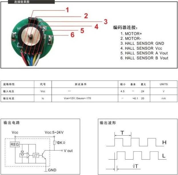
The details in this following link are ok though...https://sc01.alicdn.com/kf/HTB1e6dRGpXXXXctaXXXq6xXFXXX3/200666655/HTB1e6dRGpXXXXctaXXXq6xXFXXX3.jpg
ie.
red : motor +
black : motor -
green : hall + ... hall supply
blue : hall gnd
yellow : hall output 1
white : hall output 2
A few months late ...... but these wiring details appear to be wrong. And the link given above doesn't appear to have any reference to 3.3V.
The wiring configuration completely depends on the brand of motor. Uxcell gear motors DO follow the arrangement in the OP, so please BE SURE to accurately determine the make and model of your motors before connecting them.