HI guys, I cannot seem to get readings from my pressure sensor, It uses the RS 485 protocol and I've tried all the options I just can't get to any response. Someone please help. The name of the sensor is Qidian QDY30A. Thankyou in advance
For informed help, please read and follow the instructions in the "How to get the best out of the forum" post, linked at the head of every forum topic.
Welcome to the forum
Have you wired it to anything. It doesn't work otherwise. We are playing another game of what is in the mystery box! Have a little think about the types of information one might need to help you. The guide below will assist you
I haven't and I am wired anything but I am hoping to get signals with the arduino as master
Maybe helpful:
Thank-you, I've tried this already, and it didn't work, let me send you a sketch of my connection
A quick look for that sensor and I get a lot of hits for Chinese suppliers but very little detail regarding the method of communication. Without seeing a user manual, we would be simply guessing how to interface to this sensor.
You may be in luck if the sensor transmits the measurement every few seconds without any request for data. It may be half-duplex in that it only transmits. Again, the user manual will tell you this.
Go back to the seller and ask them for the manual.
There is a lesson here for all forum members; if you are ordering from non-official suppliers, make certain that you investigate to ensure you can get the technical details.
Sparkfun and Adafruit provide an added service for which you pay: the PDF of connections, operating drivers/libraries, and forums. This value-add seems high-priced until you consider that failure to be able to utilize your new, shinny sensor that was one-third Adafruit's price is completely useless.
And I will add, I feel that you should buy at least 2 genuine Arduinos for each model you develop: one to develop with and one as a spare hardware to check weird problems from your primary platform. The best (often only) method to differentiate software issues from hardware issues is a hardware swap.
Ultimate, even with hobby-class members, the investment in a genuine board is an investment in your sanity. Deploy your projects on clones, but do not let a clone rain on your sunny days: so much pain to save a few dollars.
Ray
1 Like
Modbus.pdf (71.1 KB)
This is the only documentation I received, but nothing more from the arduino example
Ok, we may have something to work from.
Going back to your first post:
- Which Arduino board do you have?
- Which RS485 module do you have?
- How have you wired the RS485 module to your Arduino?
- How have you wired the RS485 module to your sensor?
- How are you powering your sensor?
Post the code you have already written.
You have a choice of using a Modbus library or using canned messages.
Do you gave a USB-RS485 dongle for your PC?


/*
RS485_HalfDuplex.pde - example using ModbusMaster library to communicate
with EPSolar LS2024B controller using a half-duplex RS485 transceiver.
This example is tested against an EPSolar LS2024B solar charge controller.
See here for protocol specs:
http://www.solar-elektro.cz/data/dokumenty/1733_modbus_protocol.pdf
Library:: ModbusMaster
Author:: Marius Kintel
Copyright:: 2009-2016 Doc Walker
Licensed under the Apache License, Version 2.0 (the "License");
you may not use this file except in compliance with the License.
You may obtain a copy of the License at
http://www.apache.org/licenses/LICENSE-2.0
Unless required by applicable law or agreed to in writing, software
distributed under the License is distributed on an "AS IS" BASIS,
WITHOUT WARRANTIES OR CONDITIONS OF ANY KIND, either express or implied.
See the License for the specific language governing permissions and
limitations under the License.
*/
#include <ModbusMaster.h>
/*!
We're using a MAX485-compatible RS485 Transceiver.
Rx/Tx is hooked up to the hardware serial port at 'Serial'.
The Data Enable and Receiver Enable pins are hooked up as follows:
*/
#define MAX485_DE 3
#define MAX485_RE_NEG 2
// instantiate ModbusMaster object
ModbusMaster node;
void preTransmission()
{
digitalWrite(MAX485_RE_NEG, 1);
digitalWrite(MAX485_DE, 1);
}
void postTransmission()
{
digitalWrite(MAX485_RE_NEG, 0);
digitalWrite(MAX485_DE, 0);
}
void setup()
{
pinMode(MAX485_RE_NEG, OUTPUT);
pinMode(MAX485_a, OUTPUT);
// Init in receive mode
digitalWrite(MAX485_RE_NEG, 0);
digitalWrite(MAX485_DE, 0);
// Modbus communication runs at 115200 baud
Serial.begin(9600);
Serial.print("Got here1");
// Modbus slave ID 1
node.begin(1, Serial);
// Callbacks allow us to configure the RS485 transceiver correctly
node.preTransmission(preTransmission);
node.postTransmission(postTransmission);
Serial.print("Got here2");
}
bool state = true;
void loop()
{
uint8_t result;
uint16_t data[6];
// Toggle the coil at address 0x0002 (Manual Load Control)
result = node.writeSingleCoil(0x01, state);
state = !state;
// Read 16 registers starting at 0x3100)
result = node.readInputRegisters(0x03, 16);
if (result == node.ku8MBSuccess)
{
Serial.print("Vbatt: ");
Serial.println(node.getResponseBuffer(0x04)/100.0f);
Serial.print("Vload: ");
Serial.println(node.getResponseBuffer(0xC0)/100.0f);
Serial.print("Pload: ");
Serial.println((node.getResponseBuffer(0x0D) +
node.getResponseBuffer(0x0E) << 16)/100.0f);
}
delay(1000);
}
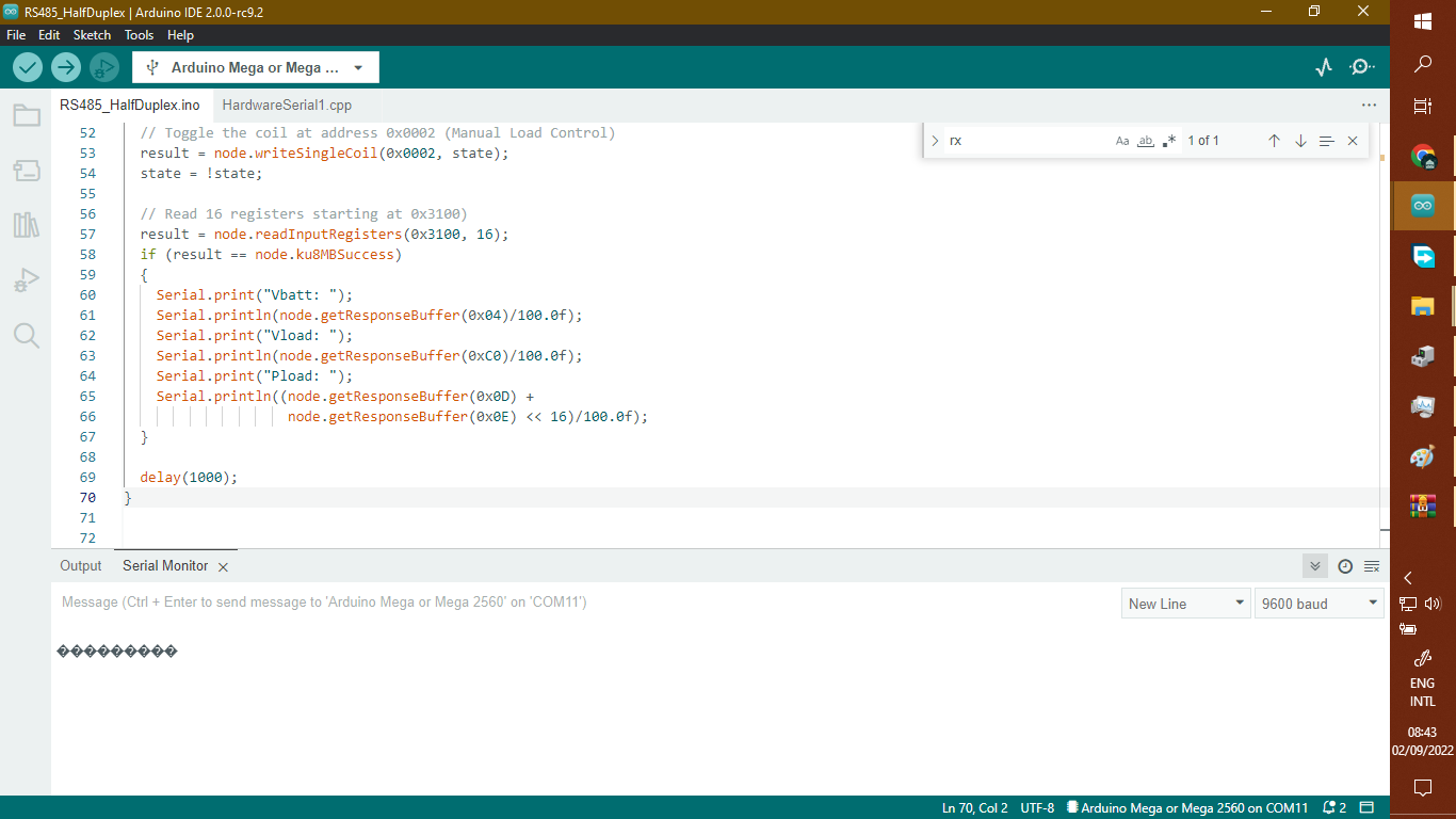
Ok, the first obvious thing is why are you using pins 0 & 1 for the RS485 comms? This is a common fudge on an UNO when people don't use a software serial port.
You have a MEGA2560 which has 4 hardware serial ports and you are using the same RS485 module that most others also use.
- Move RO to the RX1 pin, and DI to the TX1 pin.
- Add in a Serial1.begin(9600) below the existing Serial.begin(9600).
- Change node.begin(1,Serial) to node.begin(1,Serial1).
You should now be using hardware serial port #1 for your modbus comms and the standard serial port for all your uploading and printing.
This topic was automatically closed 180 days after the last reply. New replies are no longer allowed.