It is a 12volt magnetic latch, same model as this: magnetic latch
I'm powering the Uno via the onboard barrel jack from a 12V DC supply. What I'm not sure about is whether I can use the VIN pin to supply 12V to the magnet?
My understanding is that the VIN jack will bypass the regulator, allowing the magnet to use the full 12v. I'm hoping to power the board and magnet off one power supply (either plug pack, or a 12v battery at a future stage).
1/ what 12v psu are you using? enough to provide the power pulses for the relay/
2/ could you post a circuit diagram so we can see what you're doing?
3/ the arduino will only sink/source at 5v. so you'll need an h-bridge to switch the relay .
Don't power the solenoid from V-in if you power the Arduino with 12volt on the DC socket.
There is a reverse protection diode between DC socket and V-in with a max rating of 1Amp.
Leo..
Didn't know I could use a mosfet, thanks! (I'm a software guy, hardware is new to me).
I have this relay board which should do the trick instead: Relay board
I'll read up on mosfets.
Wawa:
Don't power the solenoid from V-in if you power the Arduino with 12volt on the DC socket.
There is a reverse protection diode between DC socket and V-in with a max rating of 1Amp.
The magnet only draws 100mA - wouldn't this be ok?
If not, I can make up a small harness for the power brick to split it before it hits the Arduino.
Wawa:
Don't use D1. That pin is already reserved for serial comms.
That relay board will work, but will draw ~80mA from the 5volt pin.
Don't know the "Metro". The 5volt regulator might get hot on a 12volt supply.
The gate of a mosfet draws nothing from the Arduino.
"The magnet only draws 100mA - wouldn't this be ok?"
A 2N2222 with ~1k base resistor could be used for that sort of current.
"I can make up a small harness for the power brick to split it before it hits the Arduino."
Wise.
Leo..
That's an AC relay with a triac switching element, it won't turn off by removing the gate signal.
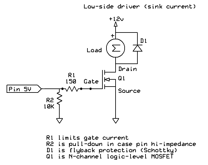
Also, you should have a "kickback" diode in parallel with the electromagnet.
outsider:
That's an AC relay with a triac switching element, it won't turn off by removing the gate signal.
Also, you should have a "kickback" diode in parallel with the electromagnet.
Would a 1N4007 be appropriate for use as a fly back diode?
It seems to be switching on and off fine in my little test circuit, but I haven't connected the magnet to it yet. I am explicitly setting the output pin LOW or HIGH in my sketch as needed.
dannyf:
Would a 1N4007 be appropriate for use as a fly back diode?
It seems to be switching on and off fine in my little test circuit, but I haven't connected the magnet to it yet. I am explicitly setting the output pin LOW or HIGH in my sketch as needed.
Yes. Almost any diode would do for a small 12volt/100mA solenoid.
The 1N5819 (schottky) would be my pick.
What test circuit. A 2N2222 with 1k base resistor?
We don't have crystal balls here.
Leo..
So the relay coil is powered by the arduino 5v pin. The relay module is capable of opto-isolation, but I have a 12v power supply with no way to step it down to 5v and power the coil (and a 2 week wait if I need additional components).
The relay you linked (NOT the solid state one) has a 5V coil so you're good to go, connect 12V+ to NO, magnet + to COM, magnet - to 12V - and don't forget the 1N4007 in parallel with the magnet, cathode (end with white stripe) toward + (toward the relay).

