Hey Folks,
When I attached my battery to my circuit the voltage starts to drop almost instantaneously. Is it possible the arduino is pulling current from the cell. When I remove the cell the voltage returns to normal.
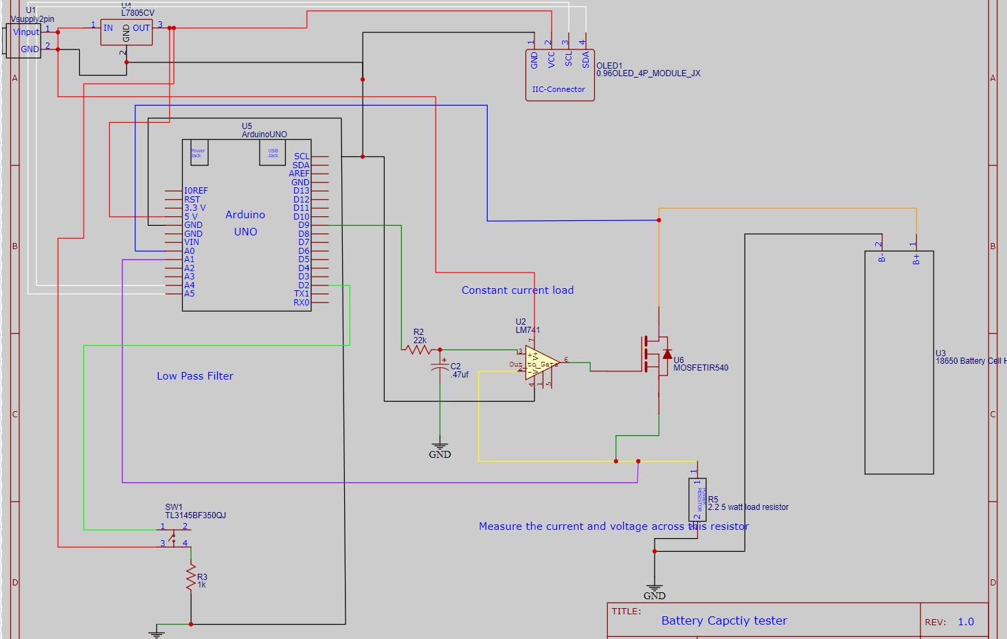
I have set up a constant current load and Pin 9 is feeding the opamp non inverting pin and inverting pin to load resistor.
I am using an IRL540 FET - so only need the 5volts to turn it on.. As I mentioned only possibility is arduino drawing current?

Please post the complete circuit, and explain what it is supposed to do.
Post links to the components.
Sorry for the messy drawing
FET - https://www.infineon.com/cms/en/product/power/mosfet/n-channel/irl540n/
2.2 5 watt load resistor
OLED display
op amp 741 with a LPF
I am using the Constant load circuit to discharge the cell - controlling the load with the PWM.
switching on and off the MOSFET
inverting pin connect to load resistor and measure voltage across this resistor. Will also calculate the current with this.
Do you think it might help to provide a bit more information?
Such as:
Is the device supposed to test a single 18650 battery, or several in series?
What is the voltage on Vinput?
Is the Arduino running any code? What might that code be doing? What have you done to check whether the code actually works?
For hints on posting, take a look through the "How to get the best out of the forum" post.
A couple of observations:
Your diagram shows that Vinput and GND are connected at U1! I trust that is not the case.
D2 is connected to SW1; when SW1 is open D2 is floating
You are taking too much current from battery. What is the value of the current ?
R5 is hot ?
Connect 2.2 ohm resistor directly to battery - it is voltage dropping rapidly ?
Connect two resistors in series
2.2x2 = 4.4 to battery - it is voltage dropping rapidly ?
The schematic is missing the required bypass capacitors on the 7805 (U4) In and Out terminals.
The estimate battery capacity, there is no real need for a constant current load. Simply measuring the voltage-time curve across a (for example) 5 Ohm load resistor is very informative.
Hi,
Do you have a DMM?
Is there a reason you have no control potentiometer the set the current?
Can you please post your code?
Thanks.. Tom.... ![]()
![]()
![]()
![]()
No worry I rushed this diagram for example purposes switches aren’t floating, appreciate the observation
r5 gets hot indeed, but Paul has pointed out the op amp isn’t rail to rail, so fet isn’t switching off
Okay it is an arduino based project for college, so I wanted to control current drain, example 1A, 500ma etc etc.
A post was split to a new topic: Constant current load design
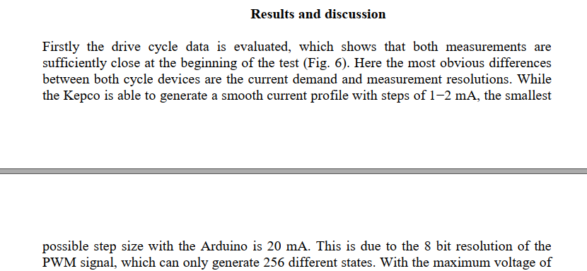
just to provide some context, this is where my idea comes from: I am not using matlab..

Ok so I have two questions In my code below I have set the PWM to 50 - and according to the paper I read each step is 20ma - so setting the PWM to 50 is 1A
But a simple google search says a pin can only supply 40ma.
So I am struggling to understand the correlation of the PWM and current.
I asked this in a previous forum and was berated.
//#include <LiquidCrystal.h>  //Default Arduino display Librarey is included
#include <Adafruit_SSD1306.h>
#include <splash.h>
#include <Adafruit_GFX.h>
#include <Wire.h>

//#include <LiquidCrystal.h>  //Default Arduino display Librarey is included
     #define SCREEN_WIDTH 128 // OLED display width, in pixels
    #define SCREEN_HEIGHT 64 // OLED display height, in pixels

    Adafruit_SSD1306 display(SCREEN_WIDTH, SCREEN_HEIGHT, &Wire, -1);
// Battery Discharge parameters
const float BAT_LOW = 2.5;    //to define the low voltage limit of the Li Ion cell
const float BAT_HIGH = 4.5;   //to define the high voltage limit of the cell
const int FET_Gate=10; // this is the pin that will connect to the gate once it foes through the OP AMP 741
const int PWM_VALUE=50; // gives a 1Amp discharge 20ma * 50 = 1A
const int buttonPin = 2; // pin 2 to start our program
int buttonState = 0; // init button state to 0 as when goes high program starts
float mA; //milliamps variable declared as is needed to calculate the Ma capacity

unsigned long intial_millis = 0; // Previous time in ms
unsigned long time_since_millis = 0;  // Current time in ms

float Capacity=0;     //Variable to define the battery Capacity
float Load_Resistor=2.2;   // Load Load_Resistor Value is 2.2

void setup() {
pinMode(buttonPin, INPUT_PULLUP);


    if (!display.begin(SSD1306_SWITCHCAPVCC, 0x3C)) {
  Serial.println(F("SSD1306 allocation failed"));
  while (true);}
  // initialize serial communication at 9600 bits per second:

  Serial.begin(9600);
   display.clearDisplay();
   display.setTextColor(WHITE);
   display.setTextSize(1);
  display.setCursor(12, 25); // Set the cursor on the first column and first row.
  display.print("Battery Capacity");
  display.setCursor(12, 36);
  display.print("Test");
  display.display();
  delay(3000);
  display.clearDisplay();
  display.setCursor(12, 25); // Set the cursor on the first column and first row.
  display.print("Push to Start");
  display.display();
  display.clearDisplay();

}


// now the loop is setup to test the battery
void loop() {

  buttonState = digitalRead(buttonPin); // reads the state of the button if it is low or high

  while (buttonState == HIGH) { // while the button is high then the loop will run .. debounce?

     display.clearDisplay();


  analogWrite(FET_Gate, PWM_VALUE);
  // read the input on analog pin 0:
  int Cell_Voltage_Sense = analogRead(A0); // reads the voltage of the cell - can serial print this
  // Convert the analog reading https://www.arduino.cc/en/Tutorial/BuiltInExamples/ReadAnalogVoltage
  float voltage = Cell_Voltage_Sense * (5.02 / 1023.0)*1.08; // measure the voltage between 5v and gnd on UNO also take Aref voltage to get accurate measurement 1.08 Aref to ground increase accuracy
  display.setCursor(8, 8); // Set the cursor
  display.print("Voltage: "); // Print the voltage reading on the screen
  display.print(voltage,2);
  display.print("V");
  //display.display();


  int Shunt_Resistor= analogRead(A1);// read the value into A1
  float voltage1= Shunt_Resistor *(5.02 / 1023.0);// 5.23 is between 5v and ground on uno
  float current= voltage1/Load_Resistor; // OHMS law

  display.setCursor(8, 25); //Set the cursor on the first column and the second row (counting starts at 0!).
  display.print("Current: "); // display current
  display.print(current,3); // display current to 3 decimal places
  display.print("A"); //A
  display.setCursor(8, 45); //Set the cursor on the first column and the second row (counting starts at 0!).
  display.print("Capacity: ");// print capacity
  display.print(Capacity,2);// capacity 2 decimals place
  display.print("mAh"); //
   display.display();
     delay(250);
   display.clearDisplay();
     display.display();


  if ( voltage > BAT_HIGH)// when the battery is high turn off the MOSFET cant discharge the circuit
  {
    digitalWrite(FET_Gate, LOW);    // Turned Off the MOSFET , No discharge
    display.setCursor(8,8);
    display.print("HIGH VOLTAGE!!");
    display.display();
    delay(200);
    display.clearDisplay();
    display.display();
  }
  else if(voltage < BAT_LOW) // when low it will display the capacity because the battery will be fully drained
  {
      digitalWrite(FET_Gate, LOW);      // Turned Off the MOSFET , No discharge
      display.setCursor(12,25);
      display.print("Low Voltage!!!");
      display.display();
      delay(300);
      display.clearDisplay();
        display.setCursor(2, 35);
    display.print("Final Capacity:");
    display.print(Capacity,1);
    display.print("mAh");
    display.setCursor(2, 15);
    display.print("Voltage:");
    display.print(voltage,1);
    display.print("V");
     display.setCursor(2, 55);
     display.print("Start Again");


    display.display();
    delay(3000);
       Serial.println(Capacity);// print to serial plotter or monitor
return;


  }
  else if(voltage > BAT_LOW && voltage < BAT_HIGH  ) // once its in between our low and high voltage then its ok to run
      time_since_millis = millis() - intial_millis;  // millis() Returns the number of milliseconds passed since the Arduino board began running the current program and previous will store whats ran
      mA = current * 1000.0 ;// current is * 1000 to get mA
      Capacity = Capacity + (mA * (time_since_millis / 3600000.0)); // 1 Hour = 3600000ms to convert this to mAh )
      intial_millis = millis();
      Serial.println(Capacity);
      Serial.println(voltage);
display.display();
      //delay(100);
      display.clearDisplay();
     }
///


  }
HI,
If you look at your circuit, the output of the UNO supplies signal to the Op-Amp.
This can be in the mA range, the Op-Amp converts this signal from a PWM to an analog voltage, by the looks of the RC network you have on the Op-Amp input.
This voltage controls the gate of the MOSFET which CONTROLS the 50mA to 2A current you need load.
The UNO does not provide the 50mA to 2A current, the MOSFET does that.
Tom.... ![]()
![]()
![]()
![]()
You are on the right track. In principle the op amp/MOSFET combination will work, but you haven't provided enough information yet to determine what is wrong with your design.
You should find this thread on constant current driver for a proportional valve to be helpful, as it has working designs: Driving proportional solenoid valve using PWM
I’m not using a rail to rail opamp so I think this is my problem.
Thanks for the link
I doubt that is the problem. The op amp needs only to supply enough voltage to activate the MOSFET, which will be in the 3-5V range.
If you will clearly answer the questions we have posted, we might be able to help.
In addition to the various circuit design comments above, the op amp is also lacking bypass capacitors and may be oscillating. You need an oscilloscope to see that.
its a single cell tester
Voltage on the input is 12volts
I have ran the code and it was running when the battery was above cut off voltage. printed to serial monitor.
So you can slap me, after getting a magnifying glass. The opamp I thought I had in wasn’t an opamp or a different code. I may have placed on my circuit when wiring until I got some… so there is my issue I think. Now I need to test again!!